EasyManuals Logo
Home>Danfoss>DC Drives>VLT Flow Drive FC 111

Danfoss VLT Flow Drive FC 111 Design Guide

Danfoss VLT Flow Drive FC 111
148 pages
To Next Page IconTo Next Page
To Previous Page IconTo Previous Page
Page #125 background imageLoading...
Page #125 background image
Field name
Example (hex)
Write byte count
04
Write registers value HI
00
Write registers value LO
00
Write registers value HI
02
Write registers value LO
0E
Error check (CRC)
Response
The normal response contains the data from the group of registers that were read. The byte count field specifies the quantity of
bytes to follow in the read data field.
Table 83: Response
Field name
Example (hex)
Follower address
01
Function
17
Byte count
04
Read registers value HI
00
Read registers value LO
00
Read registers value HI
C3
Read registers value LO
50
Error check (CRC)
8.11 Danfoss FC Control Profile
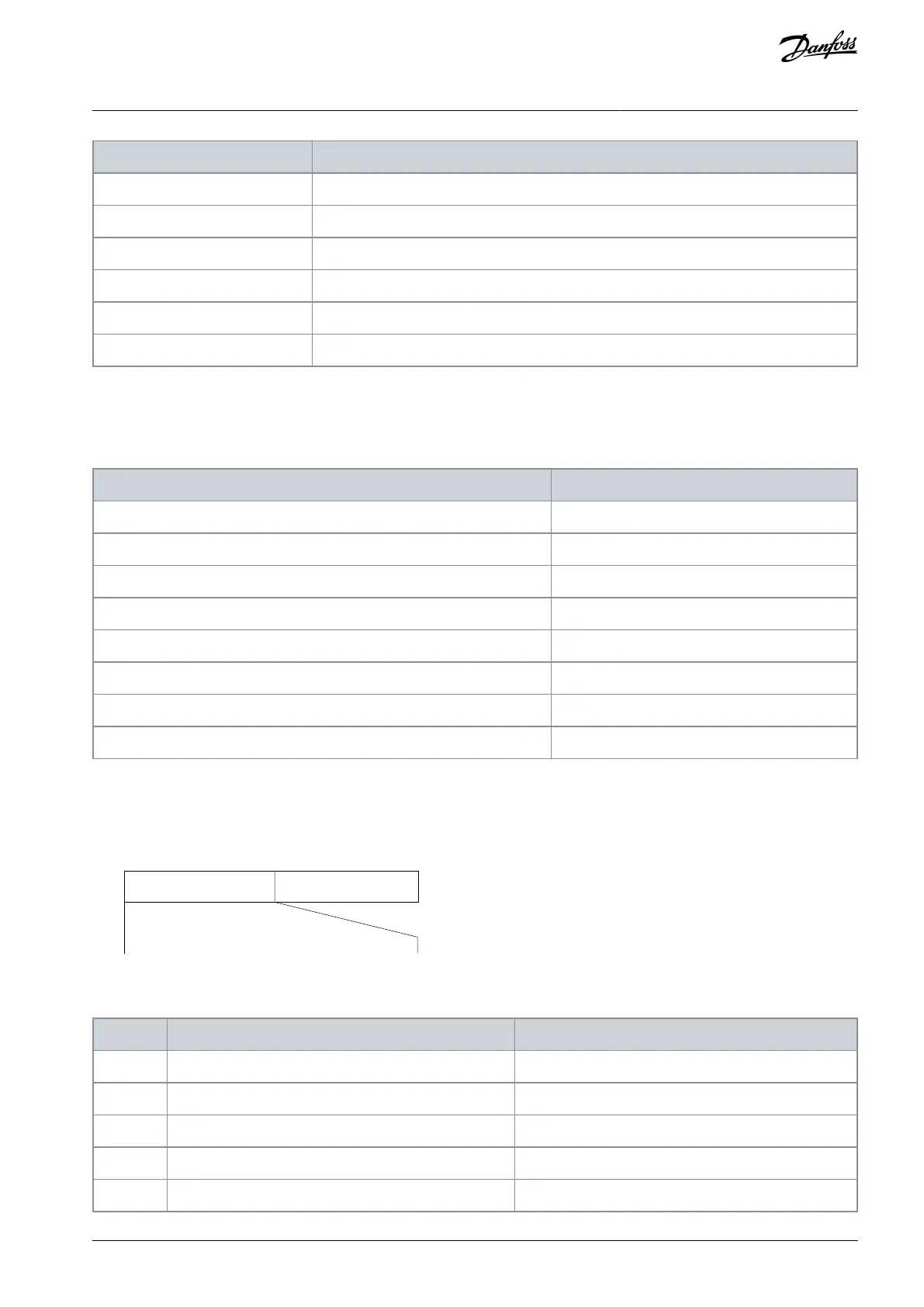
8.11.1 Control Word According to FC Profile (8-10 Protocol = FC Profile)
Speed ref.CTW
Master-follower
e30ba274.11
15 14 13 12 11 10 9 8 7 6 5 4 3 2 1 0
Bit
no.:
Illustration 78: Control Word According to FC Profile
Table 84: Control Word According to FC Profile
Bit
Bit value = 0
Bit value = 1
00
Reference value
External selection lsb
01
Reference value
External selection msb
02
DC brake
Ramp
03
Coasting
No coasting
04
Quick stop
Ramp
AJ363928382091en-000101 / 130R0983 | 125Danfoss A/S © 2021.04
RS485 Installation and Set-up
VLT® Flow Drive FC 111
Design Guide

Table of Contents

Other manuals for Danfoss VLT Flow Drive FC 111

Questions and Answers:

Question and Answer IconNeed help?

Do you have a question about the Danfoss VLT Flow Drive FC 111 and is the answer not in the manual?

Danfoss VLT Flow Drive FC 111 Specifications

General IconGeneral
BrandDanfoss
ModelVLT Flow Drive FC 111
CategoryDC Drives
LanguageEnglish

Related product manuals