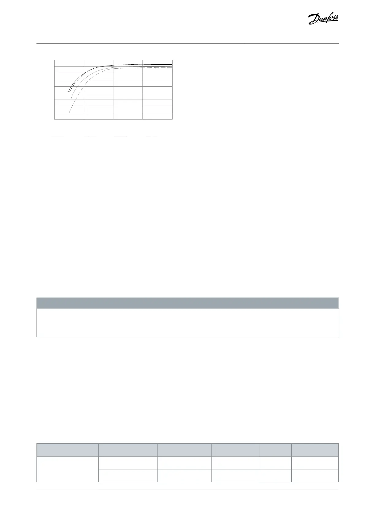
0.98
0.97
0.96
0.95
0.93
0.92
0%
100% load 75% load 50% load 25% load
Illustration 58: Typical Efficiency Curves
6.11.2 Efficiency of the Motor
The efficiency of a motor (η
MOTOR
) connected to the drive depends on the magnetizing level. In general, the efficiency is as good as
with mains operation. The efficiency of the motor depends on the type of motor.
In the range of 75–100% of the rated torque, the efficiency of the motor is practically constant, both when controlled by the drive
and when running directly on mains.
In small motors, the influence from the U/f characteristic on efficiency is marginal. However, in motors from 11 kW (15 hp) and up,
the advantages are significant.
In general, the switching frequency does not affect the efficiency of small motors. Motors from 11 kW (15 hp) and up have their
efficiency improved 1–2% because the sine shape of the motor current is almost perfect at high switching frequency.
6.11.3 Efficiency of the System
To calculate the system efficiency (η
SYSTEM
), the efficiency of the drive (η
VLT
) is multiplied by the efficiency of the motor (η
MOTOR
):
η
SYSTEM
= η
VLT
x η
MOTOR
6.12 dU/dt Conditions
6.12.1 dU/dt Overview
N O T I C E
To avoid the premature aging of motors that are not designed to be used with drives, such as those motors without phase insula-
tion paper or other insulation reinforcement, Danfoss strongly recommends a dU/dt filter or a sine-wave filter fitted on the out-
put of the drive. For further information about dU/dt and sine-wave filters, see the Output Filters Design Guide.
When a transistor in the inverter bridge switches, the voltage across the motor increases by a dU/dt ratio depending on the motor
cable (type, cross-section, length shielded or unshielded) and the inductance.
The natural induction causes an overshoot U
PEAK
in the motor voltage before it stabilizes itself at a level depending on the voltage
in the intermediate circuit. The rise time and the peak voltage U
PEAK
affect the service life of the motor. In particular, motors without
phase coil insulation are affected if the peak voltage is too high. Motor cable length affects the rise time and peak voltage. If the
motor cable is short (a few meters), the rise time and peak voltage are lower. If the motor cable is long (100 m (328 ft)), the rise time
and peak voltage are higher.
Peak voltage on the motor terminals is caused by the switching of the IGBTs. The drive complies with the demands of IEC
60034-25:2007 edition 2.0 regarding motors designed to be controlled by drives. The drive also complies with IEC 60034-17:2006
edition 4 regarding Norm motors controlled by drives.
6.12.2 dU/dt Test Results for H1–H8
Table 40: dU/dt Test Results for H1–H8
AJ363928382091en-000101 / 130R0983 | 77Danfoss A/S © 2021.04
Electrical Installation
Considerations
VLT® Flow Drive FC 111
Design Guide
 Loading...


