1.
5.3.5 Creating Cable Openings
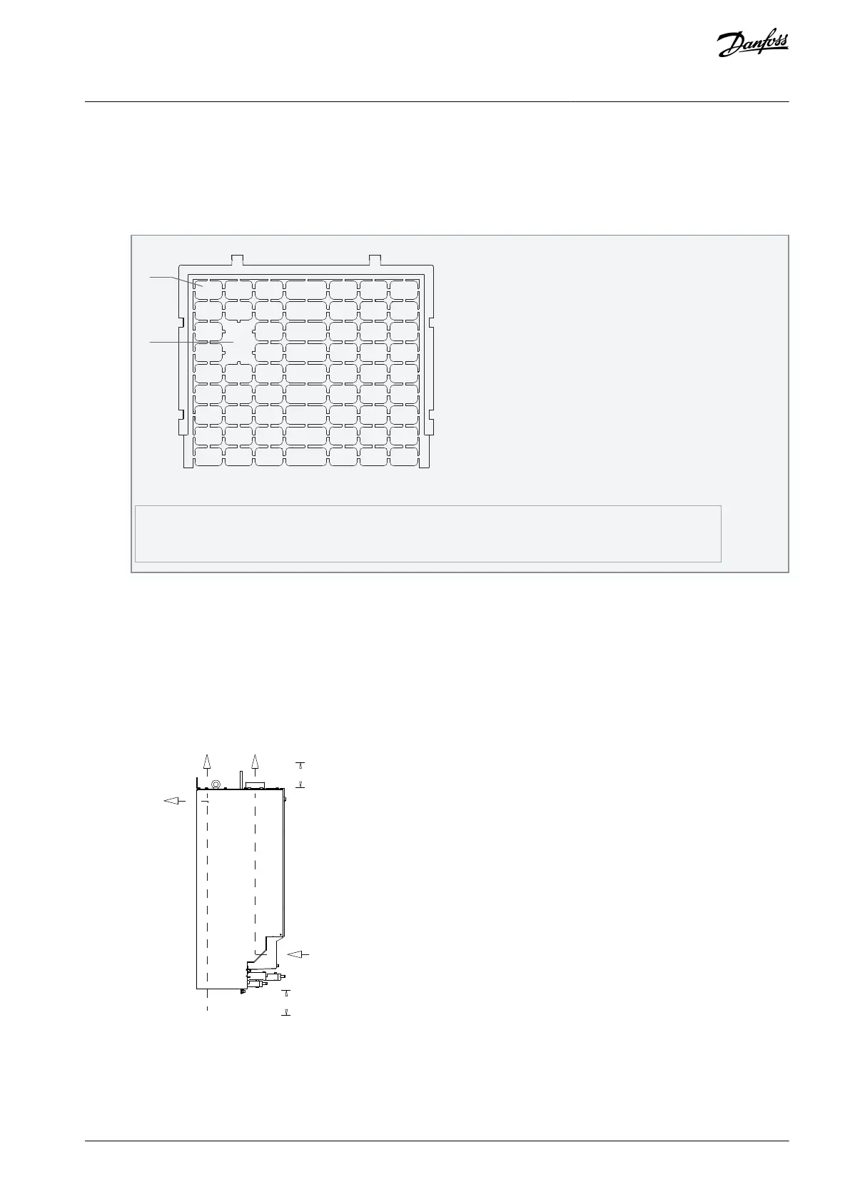
After installing the drive, create cable openings in the gland plate to accommodate the mains and motor cables. The gland plate is
required to maintain the drive protection rating.
Procedure
Punch out plastic tabs to accommodate the cables.
Illustration 44: Cable Openings in Plastic Gland Plate
Tabs removed for cable access
5.3.6 Back-channel Cooling
A unique back-channel duct passes cooling air over the heat sinks with minimal air passing through the electronics area. There is an
IP54/Type 12 seal between the back-channel cooling duct and the electronics area of the VLT® drive. This back-channel cooling
allows 90% of the heat losses to be exhausted directly outside the enclosure. This design improves reliability and prolongs compo-
nent life by dramatically reducing interior temperatures and contamination of the electronic components. Different back-channel
cooling kits are available to redirect the airflow based on individual needs.
5.3.6.1 Airflow for H13 & H14 Enclosures
e30bg823.10
225 mm (8.9 in)
225 mm (8.9 in)
Illustration 45: Standard Airflow Configuration for Enclosures H13 and H14
AJ363928382091en-000101 / 130R0983 | 59Danfoss A/S © 2021.04
Mechanical Installation
Considerations
VLT® Flow Drive FC 111
Design Guide
 Loading...


