EasyManuals Logo
Home>Danfoss>DC Drives>VLT Flow Drive FC 111

Danfoss VLT Flow Drive FC 111 Design Guide

Danfoss VLT Flow Drive FC 111
148 pages
To Next Page IconTo Next Page
To Previous Page IconTo Previous Page
Page #69 background imageLoading...
Page #69 background image
6.4.5 Relays and Terminals on Enclosure Size H13–H14
e30bu777 .10
1
2
3
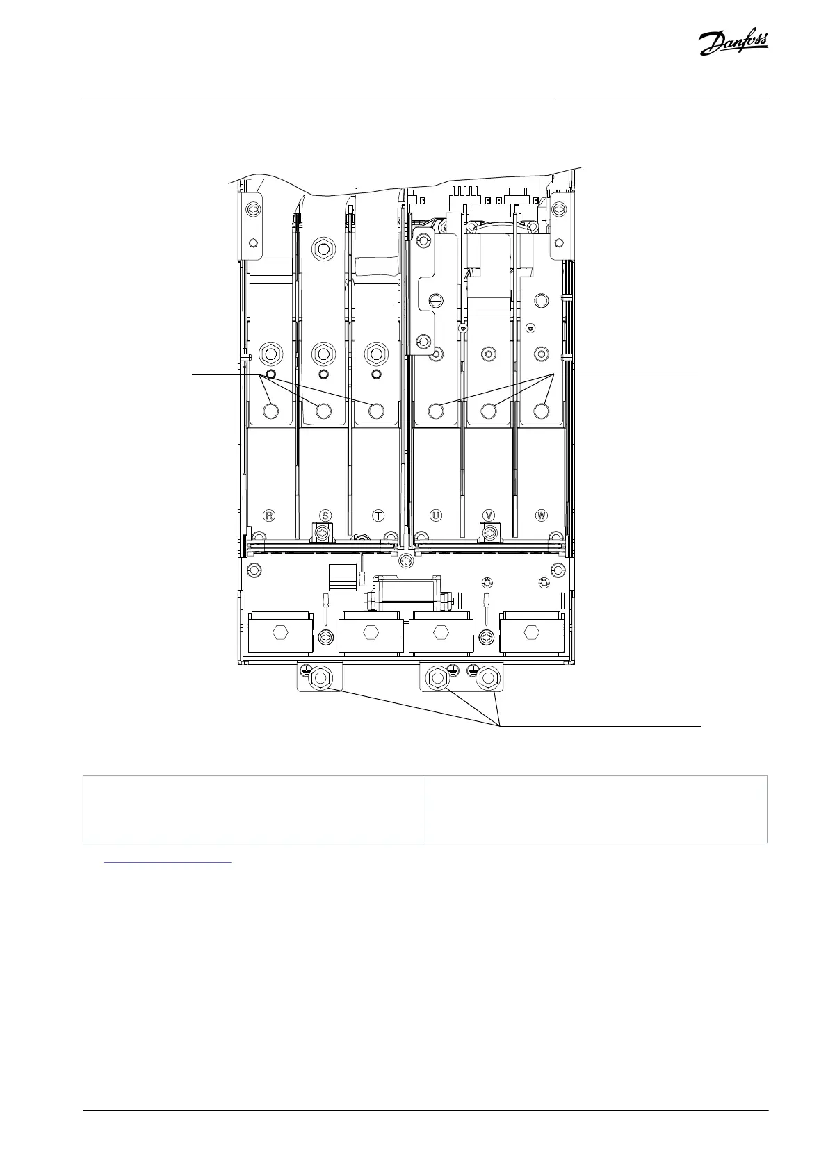
Illustration 52: Enclosure Size H13–H14 IP20, 380–480 V, 110–315 kW (150–450 hp)
1
Mains
2
Motor
3
Ground
See 6.5 View of Control Shelf for the relay terminals of H13–H14 drives.
6.5 View of Control Shelf
The control shelf of H13-H14 drives holds the keypad, known as the local control panel or LCP. The control shelf also includes the
control terminals, relays, and various connectors.
AJ363928382091en-000101 / 130R0983 | 69Danfoss A/S © 2021.04
Electrical Installation
Considerations
VLT® Flow Drive FC 111
Design Guide

Table of Contents

Other manuals for Danfoss VLT Flow Drive FC 111

Questions and Answers:

Question and Answer IconNeed help?

Do you have a question about the Danfoss VLT Flow Drive FC 111 and is the answer not in the manual?

Danfoss VLT Flow Drive FC 111 Specifications

General IconGeneral
BrandDanfoss
ModelVLT Flow Drive FC 111
CategoryDC Drives
LanguageEnglish

Related product manuals