EasyManuals Logo
Home>Danfoss>DC Drives>VLT Flow Drive FC 111

Danfoss VLT Flow Drive FC 111 Design Guide

Danfoss VLT Flow Drive FC 111
148 pages
To Next Page IconTo Next Page
To Previous Page IconTo Previous Page
Page #131 background imageLoading...
Page #131 background image
9 General Specifications
9.1 Mains Supply
9.1.1 3x380–480 V AC
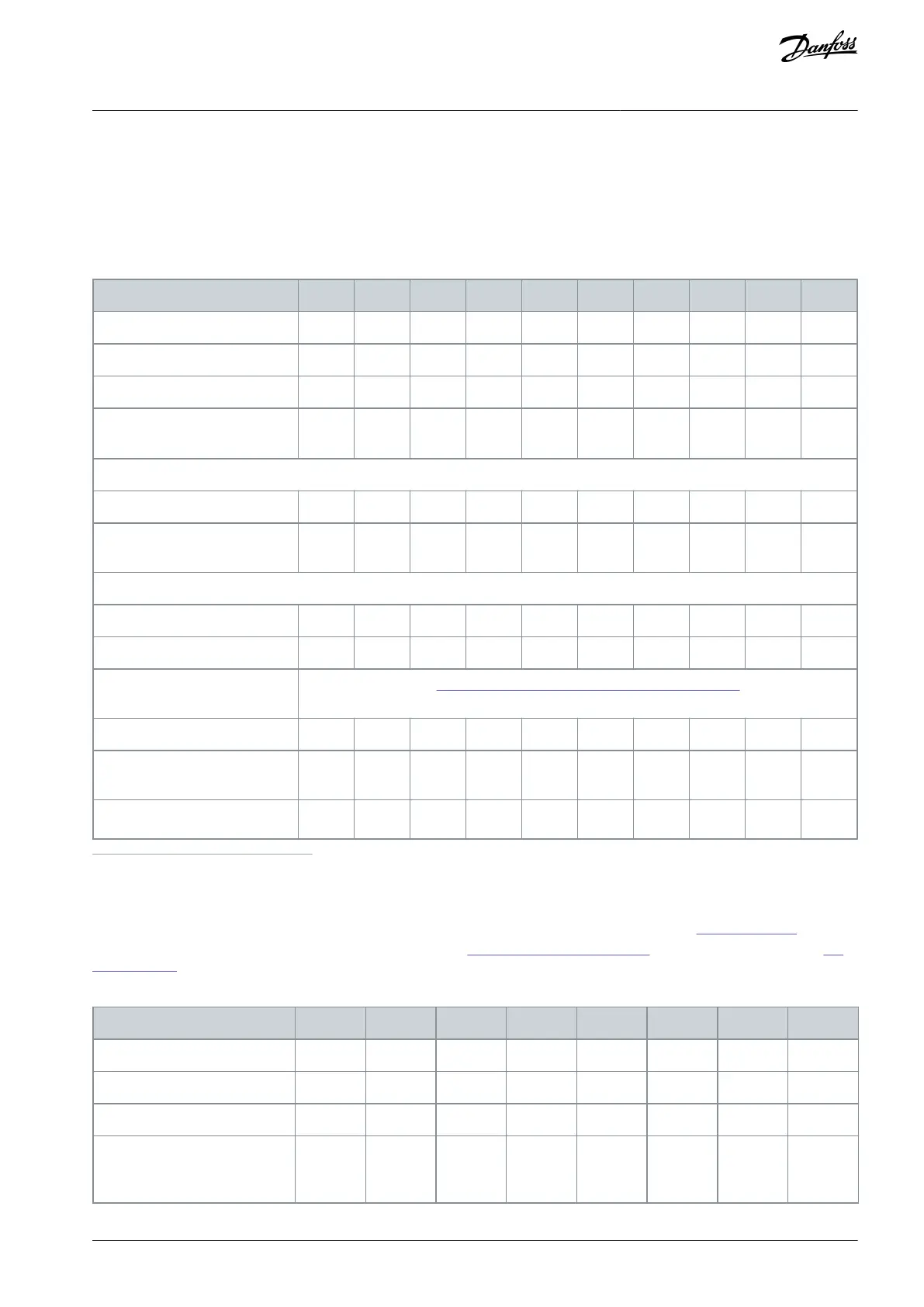
Table 88: 3x380–480 V AC, 0.37–15 kW (0.5–20 hp), Enclosure Sizes H1–H4
Drive
PK37
PK75
P1K5
P2K2
P3K0
P4K0
P5K5
P7K5
P11K
P15K
Typical shaft output [kW]
0.37
0.75
1.5
2.2
3.0
4.0
5.5
7.5
11.0
15.0
Typical shaft output [hp]
0.5
1.0
2.0
3.0
4.0
5.4
7.5
10.0
15.0
20.0
Protection rating IP20
H1
H1
H1
H2
H2
H2
H3
H3
H4
H4
Maximum cable size in terminals
(mains, motor) [mm
2
(AWG)]
4 (10)
4 (10)
4 (10)
4 (10)
4 (10)
4 (10)
4 (10)
4 (10)
16 (6)
16 (6)
Output current at 40°C (104°F) ambient temperature
(1)
Continuous [A]
1.2
2.2
3.7
5.3
7.2
9.0
12.0
15.5
23.0
31.0
Intermittent (110% overload 60
s) [A]
(2)
1.3
2.4
4.1
5.8
7.9
9.9
13.2
17.1
25.3
34.0
Maximum input current
Continuous [A]
1.2
2.1
3.5
4.7
6.3
8.3
11.2
15.1
22.1
29.9
Intermittent [A]
1.3
2.3
3.9
5.2
6.9
9.1
12.3
16.6
24.3
32.9
Maximum external mains fuses
[A]
See 6.9.5 Recommendation of Fuses and Circuit Breakers.
Estimated power loss [W]
(3)
15
21
57
58
83
118
131
198
274
379
Weight enclosure protection rat-
ing IP20 [kg (lb)]
2.0
(4.4)
2.0
(4.4)
2.1
(4.6)
3.3
(7.3)
3.3
(7.3)
3.4
(7.5)
4.3
(9.5)
4.5
(9.9)
7.9
(17.4)
7.9
(17.4)
Efficiency [%]
(4)
97.3
97.6
97.2
97.9
97.8
97.6
98.0
97.8
97.9
97.8
1
Refer to the chapter Derating for the derating curves at 50°C (122°F) ambient temperature.
2
The drive also supports 150% overload for 60 s when selecting 1 level higher power size.
3
Applies for dimensioning of drive cooling. If the switching frequency is higher than the default setting, the power losses may increase. LCP and
typical control card power consumptions are included. For power loss data according to EN 50598-2, refer to Danfoss
MyDrive® ecoSmart website.
4
Efficiency measured at nominal current. For energy efficiency class, see 9.2.13 Ambient Conditions (H1–H8). For part load losses, see Danfoss My-
Drive® ecoSmart website.
Table 89: 3x380–480 V AC, 18.5–90 kW (25–125 hp), Enclosure Sizes H5–H8
Drive
P18K
P22K
P30K
P37K
P45K
P55K
P75K
P90K
Typical shaft output [kW]
18.5
22.0
30.0
37.0
45.0
55.0
75.0
90.0
Typical shaft output [hp]
25.0
30.0
40.0
50.0
60.0
70.0
100.0
125.0
Protection rating IP20
H5
H5
H6
H6
H6
H7
H7
H8
Maximum cable size in termi-
nals (mains, motor) [mm
2
(AWG)]
16 (6)
16 (6)
35 (2)
35 (2)
35 (2)
50 (1)
95 (0)
120 (250
MCM)
AJ363928382091en-000101 / 130R0983 | 131Danfoss A/S © 2021.04
General Specifications
VLT® Flow Drive FC 111
Design Guide

Table of Contents

Other manuals for Danfoss VLT Flow Drive FC 111

Questions and Answers:

Question and Answer IconNeed help?

Do you have a question about the Danfoss VLT Flow Drive FC 111 and is the answer not in the manual?

Danfoss VLT Flow Drive FC 111 Specifications

General IconGeneral
BrandDanfoss
ModelVLT Flow Drive FC 111
CategoryDC Drives
LanguageEnglish

Related product manuals