3.2.2 IT Line Power
CAUTION
IT Line Power
Installation on isolated line power source, that is, IT line
power.
Ensure the supply voltage does not exceed 440 V
(3x380-480 V units) when connected to line power.
On IP20, 200-240 V, 0.25-11 kW (0.33-15 HP) and 380-480
V, IP20, 0.37-22 kW (0.5-30 HP) units, open the RFI switch
by removing the screw on the side of the adjustable
frequency drive when at IT grid.
1 EMC screw
Figure 3.1 IP20, 200-240 V, 0.25-11 kW (0.33-15 HP), IP20,
0.37-22 kW (0.5-30 HP), 380-480 V
On 400 V, 30-90 kW (40-125 HP) and 600 V units, set
14-50 RFI Filter to [0] Off when operating in IT line power.
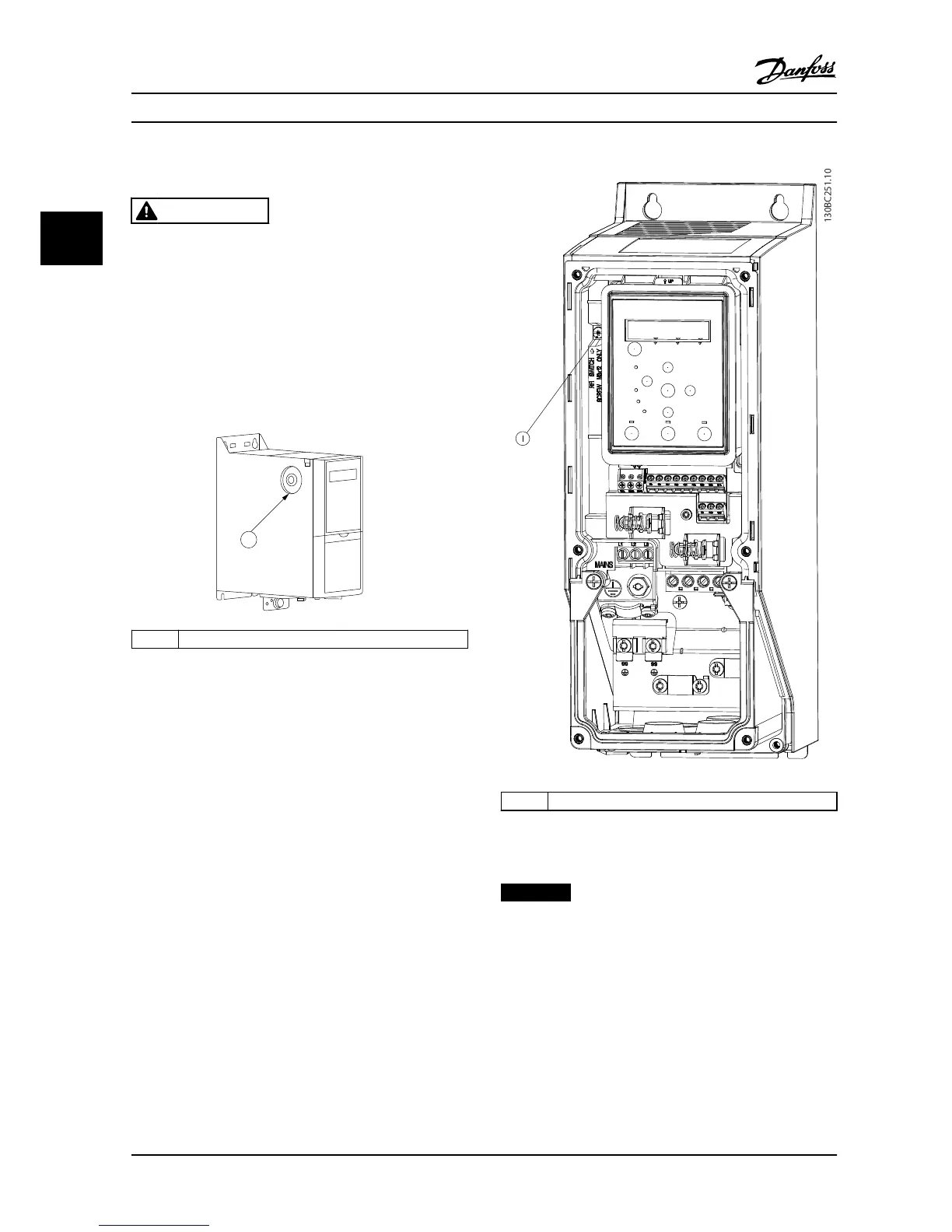
For IP54, 400V, 0.75-18.5 kW (1-25 HP) units, the EMC
screw is inside the adjustable frequency drive, as shown in
Figure 3.2.
1
EMC screw
Figure 3.2 IP54, 400 V, 0.75-18.5 kW (1-25 HP)
NOTICE!
If reinserted, use only M3x12 screw.
3.2.3 Connecting to Line Power and Motor
The adjustable frequency drive is designed to operate all
standard 3-phase asynchronous motors. For maximum
cross-section on cables, see chapter 6.4 General Technical
Data.
•
Use a shielded/armored motor cable to comply
with EMC emission specifications, and connect
Installation
VLT®HVAC Basic Drive FC 101
10 Danfoss A/S © 08/2014 All rights reserved. MG18A622
33
 Loading...


