4 Programming
4.1 Local Control Panel (LCP)
NOTICE!
The adjustable frequency drive can also be programmed
from a PC via the RS-485 COM port by installing the MCT
10 Set-up Software. Refer to chapter 1.2.1 MCT 10 Set-up
Software Support for more details about the software.
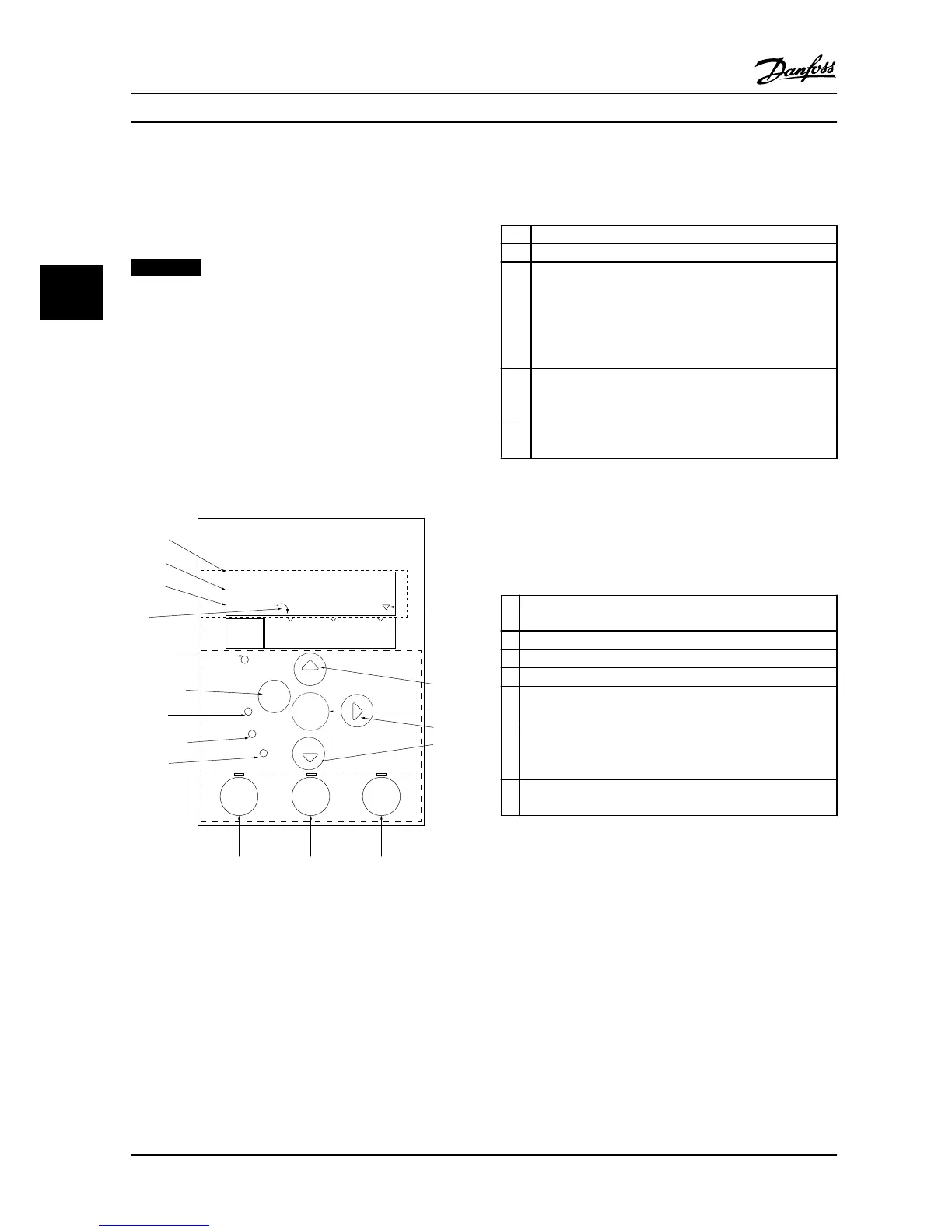
The LCP is divided into four functional sections.
A. Display
B. Menu key
C. Navigation keys and LEDs
D. Operation keys and LEDs
Figure 4.1 Local Control Panel (LCP)
A. Display
The LCD display is backlit with two alphanumeric lines. All
data is displayed on the LCP.
Figure 4.1 describes the information that can be read from
the display.
1
Parameter number and name.
2 Parameter value.
3 Set-up number shows the active set-up and the edit set-
up. If the same set-up acts as both the active and edit set-
up, only that set-up number is shown (factory setting).
When active and edit set-up differ, both numbers are
shown in the display (Set-up 12). The flashing number
indicates the edit set-up.
4 Motor direction is shown to the bottom left of the display
– indicated by a small arrow pointing either clockwise or
counter-clockwise.
5 The triangle indicates if the LCP is in status quick menu or
main menu.
Table 4.1 Legend to Figure 4.1
B. Menu key
Press [Menu] to select between status, quick menu or main
menu.
C. Navigation keys and LEDs
6 Com LED: Flashes when bus communication is communi-
cating.
7 Green LED/On: Control section is working correctly.
8 Yellow LED/Warn.: Indicates a warning.
9 Flashing Red LED/Alarm: Indicates an alarm.
10 [Back]: For moving to the previous step or layer in the
navigation structure.
11
[
▲
] [
▼
] [►]: For navigating among parameter groups,
parameters and within parameters. They can also be used for
setting local reference.
12 [OK]: For selecting a parameter and for accepting changes to
parameter settings.
Table 4.2 Legend to Figure 4.1
Programming VLT®HVAC Basic Drive FC 101
26 Danfoss A/S © 08/2014 All rights reserved. MG18A622
44
 Loading...


