3 Installation
3.1 Mechanical Installation
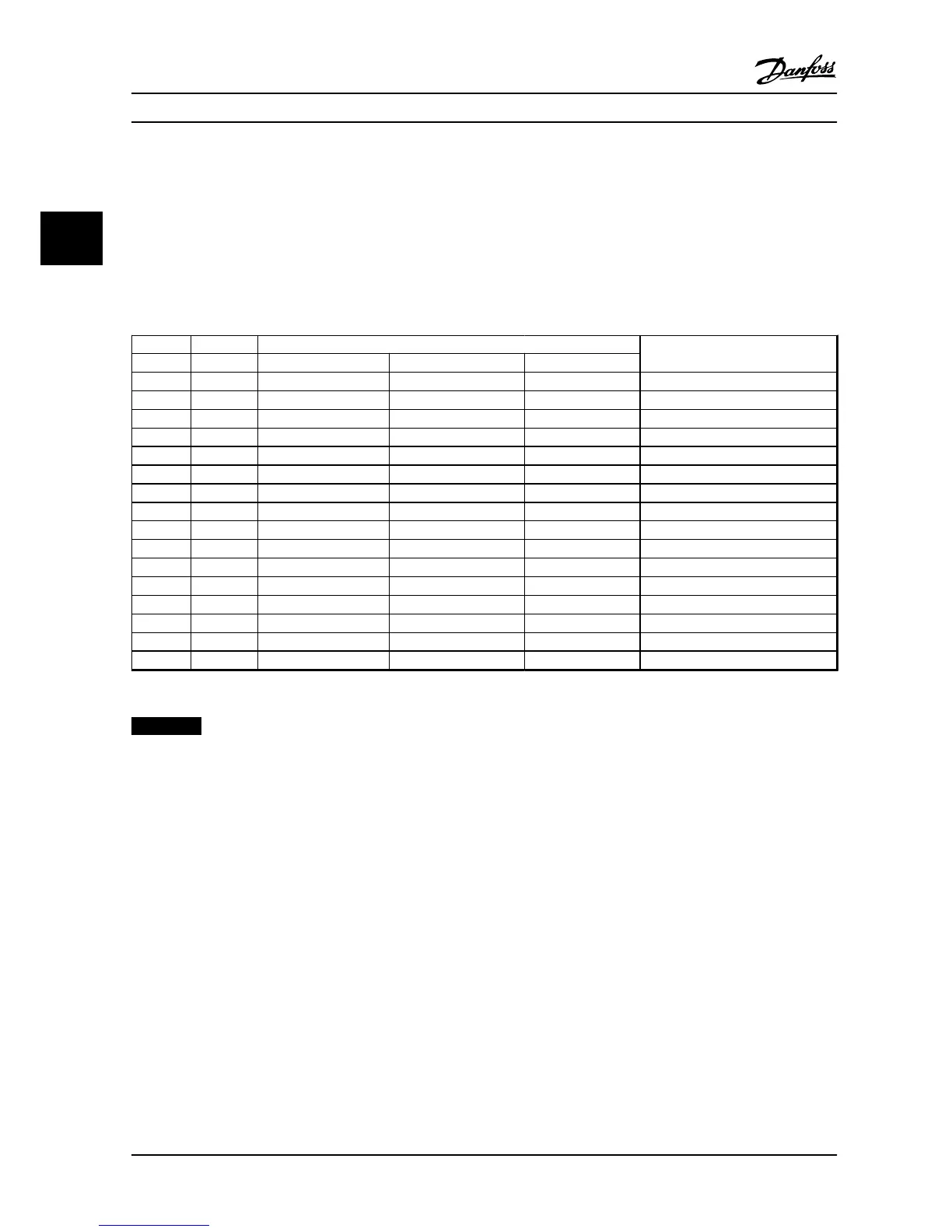
3.1.1 Side-by-Side Installation
The adjustable frequency drive can be mounted side-by-side but requires the clearance above and below for cooling.
Power [kW (HP)]
Clearance above/below [mm (in)]
Frame IP class 3x200-240 V 3x380-480 V 3x525-600 V
H1 IP20 0.25-1.5 (0.33-2) 0.37-1.5 (0.5-2) – 100 (4)
H2 IP20 2.2 (3) 2.2-4 (3-5) – 100 (4)
H3 IP20 3.7 (5) 5.5-7.5 (7.5-10) – 100 (4)
H4 IP20 5.5-7.5 (7.5-10) 11-15 (15-20) – 100 (4)
H5 IP20 11 (15) 18.5-22 (25-30) – 100 (4)
H6 IP20 15-18.5 (20-25) 30-45 (40-60) 18.5-30 (25-40) 200 (7.9)
H7 IP20 22-30 (30-40) 55-75 (70-100) 37-55 (50-70) 200 (7.9)
H8 IP20 37-45 (50-60) 90 (125) 75-90 (100-125) 225 (8.9)
H9 IP20 – – 2.2-7.5 (3-10) 100 (4)
H10 IP20 – – 11-15 (15-20) 200 (7.9)
I2 IP54 – 0.75-4.0 (1-5) – 100 (4)
I3 IP54 – 5.5-7.5 (7.5-10) – 100 (4)
I4 IP54 – 11-18.5 (15-25) – 100 (4)
I6 IP54 – 22-37 (30-50) – 200 (7.9)
I7 IP54 – 45-55 (60-70) – 200 (7.9)
I8 IP54 – 75-90 (100-125) – 225 (8.9)
Table 3.1 Clearance Required for Cooling
NOTICE!
With IP21/NEMA Type1 option kit mounted, a distance of 50 mm (2 in) between the units is required.
Installation VLT®HVAC Basic Drive FC 101
6 Danfoss A/S © 08/2014 All rights reserved. MG18A622
33
 Loading...


