6 Specifications
6.1 Line Power Supply
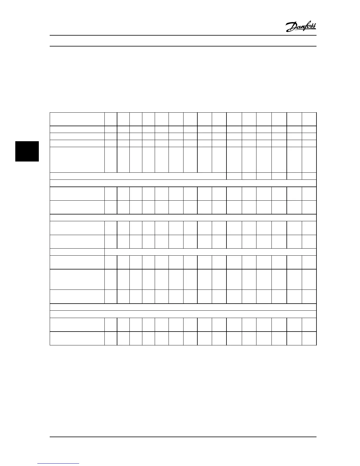
6.1.1 3x200–240 V AC
Adjustable frequency
drive
PK25 PK37 PK75 P1K5 P2K2 P3K7 P5K5 P7K5 P11K P15K P18K P22K P30K P37K P45K
Typical shaft output [kW] 0.25 0.37 0.75 1.5 2.2 3.7 5.5 7.5 11.0 15.0 18.5 22.0 30.0 37.0 45.0
Typical shaft output [HP] 0.33 0.5 1.0 2.0 3.0 5.0 7.5 10.0 15.0 20.0 25.0 30.0 40.0 50.0 60.0
IP20 frame H1 H1 H1 H1 H2 H3 H4 H4 H5 H6 H6 H7 H7 H8 H8
Maximum cable size in
terminals (line power,
motor) [mm
2
(AWG)]
4
(10)
4
(10)
4
(10)
4
(10)
4 (10) 4 (10) 16 (6) 16 (6) 16 (6) 35 (2) 35 (2) 50 (1) 50 (1) 95 (0) 120
(4/0)
Output current
40 °C (104 °F) ambient temperature
Continuous
(3x200–240 V) [A]
1.5 2.2 4.2 6.8 9.6 15.2 22.0 28.0 42.0 59.4 74.8 88.0 115.0 143.0 170.0
Intermittent
(3x200–240 V) [A]
1.7 2.4 4.6 7.5 10.6 16.7 24.2 30.8 46.2 65.3 82.3 96.8 126.5 157.3 187.0
Maximum input current
Continuous
(3x200–240 V) [A]
1.1 1.6 2.8 5.6 8.6/
7.2
14.1/
12.0
21.0/
18.0
28.3/
24.0
41.0/
38.2
52.7 65.0 76.0 103.7 127.9 153.0
Intermittent
(3x200–240 V) [A]
1.2 1.8 3.1 6.2 9.5/
7.9
15.5/
13.2
23.1/
19.8
31.1/
26.4
45.1/
42.0
58.0 71.5 83.7 114.1 140.7 168.3
Maximum electrical fuses
See chapter 3.2.4 Fuses and Circuit Breakers
Estimated power loss [W],
Best case/typical1)
12/
14
15/
18
21/
26
48/
60
80/
102
97/
120
182/
204
229/
268
369/
386
512 697 879 1149 1390 1500
Weight enclosure IP20 [kg
(lb)]
2.0
(4.4)
2.0
(4.4)
2.0
(4.4)
2.1
(4.6)
3.4
(7.5)
4.5
(9.9)
7.9
(17.4)
7.9
(17.4)
9.5
(20.9)
24.5
(54)
24.5
(54)
36.0
(79.4)
36.0
(79.4)
51.0
(112.4
)
51.0
(112.4
)
Efficiency [%], best case/
typical
2)
97.0/
96.5
97.3/
96.8
98.0/
97.6
97.6/
97.0
97.1/
96.3
97.9/
97.4
97.3/
97.0
98.5/
97.1
97.2/
97.1
97.0 97.1 96.8 97.1 97.1 97.3
Output current
50 °C (122 °F) ambient temperature
Continuous
(3x200–240 V) [A]
1.5 1.9 3.5 6.8 9.6 13.0 19.8 23.0 33.0 41.6 52.4 61.6 80.5 100.1 119
Intermittent
(3x200–240 V) [A]
1.7 2.1 3.9 7.5 10.6 14.3 21.8 25.3 36.3 45.8 57.6 67.8 88.6 110.1 130.9
Table 6.1 3x200–240 V AC, 0.25–45 kW (0.33–60 HP)
1) Applies for dimensioning of adjustable frequency drive cooling. If the switching frequency is higher than the default setting, the power losses
may increase. LCP and typical control card power consumptions are included. For power loss data according to EN 50598-2, refer to
www.danfoss.com/vltenergyefficiency.
2) Efficiency measured at nominal current. For energy efficiency class, see chapter 6.4.13 Ambient Conditions. For part load losses, see
www.danfoss.com/vltenergyefficiency.
Specifications VLT®HVAC Basic Drive FC 101
46 Danfoss A/S © 08/2014 All rights reserved. MG18A622
66
 Loading...


