EasyManuals Logo
Home>Danfoss>DC Drives>VLT HVAC Basic Drive FC 101

Danfoss VLT HVAC Basic Drive FC 101 User Manual

Danfoss VLT HVAC Basic Drive FC 101
62 pages
To Next Page IconTo Next Page
To Previous Page IconTo Previous Page
Page #25 background imageLoading...
Page #25 background image
3.2.6 Control Terminals
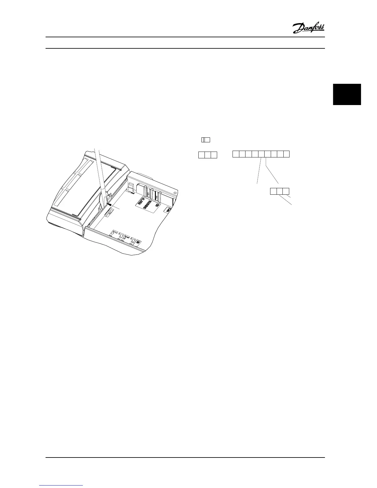
Remove the terminal cover to access the control terminals.
Use a flat-edged screwdriver to push down the lock lever
of the terminal cover under the LCP, then remove the
terminal cover, as shown in Figure 3.22.
For IP54 units, remove the front cover before removing the
terminal cover.
130BD331.10
Figure 3.22 Removing the Terminal Cover
Control terminals
Figure 3.23 shows all the adjustable frequency drive control
terminals. Applying Start (terminal 18), connection
between terminal 12-27, and an analog reference (terminal
53 or 54 and 55) make the adjustable frequency drive run.
The digital input mode of terminal 18, 19, and 27 is set in
5-00 Digital Input Mode (PNP is default value). Digital input
29 mode is set in 5-03 Digital Input 29 Mode (PNP is default
value).
18
19
12 20 55
27 29 42 45 50 53 54
DIGI IN
DIGI IN
DIGI IN
DIGI IN
61 68 69
N
P
COMM. GND
+24V
0/4-20mA A OUT / DIG OUT 0/4-20mA A OUT / DIG OUT
GND
GND
10V/20mA IN
10V/20mA IN
10V OUT
130BB625.10
BUS TER.
OFF ON
Figure 3.23 Control Terminals
Installation Quick Guide
MG18A622 Danfoss A/S © 08/2014 All rights reserved. 23
3 3

Other manuals for Danfoss VLT HVAC Basic Drive FC 101

Questions and Answers:

Question and Answer IconNeed help?

Do you have a question about the Danfoss VLT HVAC Basic Drive FC 101 and is the answer not in the manual?

Danfoss VLT HVAC Basic Drive FC 101 Specifications

General IconGeneral
BrandDanfoss
ModelVLT HVAC Basic Drive FC 101
CategoryDC Drives
LanguageEnglish

Related product manuals