L1
L2
L3
3 Phase
power
input
PE
PE
+10 V DC
0-10 V DC-
0-10 V DC-
50 (+10 V OUT)
54 (A IN)
53 (A IN)
55 (COM A IN/OUT)
0/4-20 mA
0/4-20 mA
42 0/4-20 mA A OUT / DIG OUT
45 0/4-20 mA A OUT / DIG OUT
18 (DIGI IN)
19 (DIGI IN)
27 (DIGI IN)
29 (DIGI IN)
12 (+24 V OUT)
24 V (NPN)
20 (COM D IN)
O V (PNP)
24 V (NPN)
O V (PNP)
24 V (NPN)
O V (PNP)
24 V (NPN)
O V (PNP)
Bus ter.
Bus ter.
RS-485
Interface
RS-485
(N PS-485) 69
(P RS-485) 68
(Com RS-485 ) 61
(PNP)-Source
(NPN)-Sink
ON=Terminated
OFF=Unterminated
ON
1 2
240 V AC 3 A
Not present on all power sizes
Do not connect shield to 61
01
02
03
relay1
relay2
UDC+
UDC-
Motor
U
V
W
130BD467.10
06
05
04
240 V AC 3 A
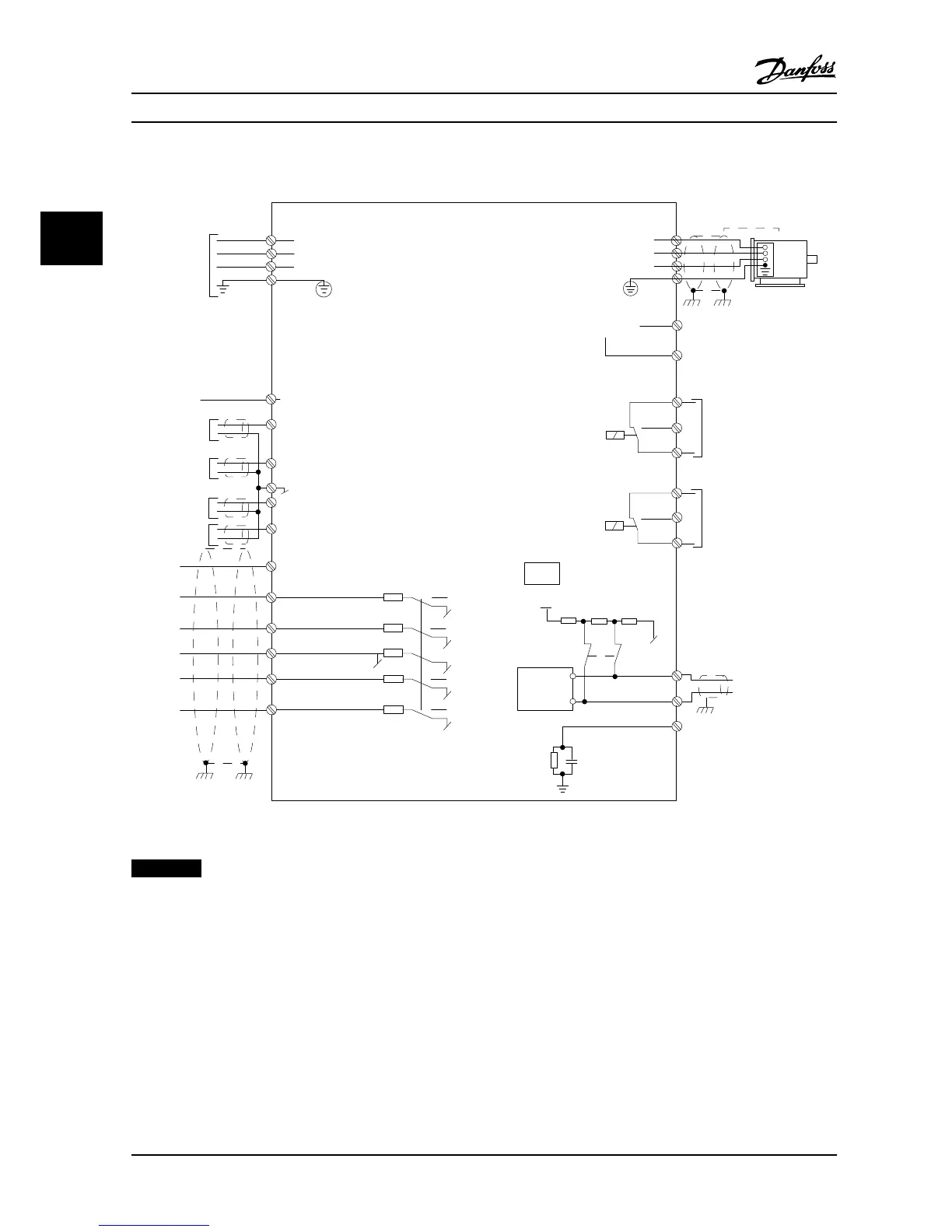
Figure 3.24 Basic Wiring Schematic Drawing
NOTICE!
There is no access to UDC- and UDC+ on the following units:
IP20, 380–480 V, 30–90 kW (40–125 HP)
IP20, 200–240 V, 15–45 kW (20–60 HP)
IP20, 525–600 V, 2.2–90 kW (3–125 HP)
IP54, 380–480 V, 22–90 kW (30–125 HP)
Installation VLT®HVAC Basic Drive FC 101
24 Danfoss A/S © 08/2014 All rights reserved. MG18A622
33
 Loading...


