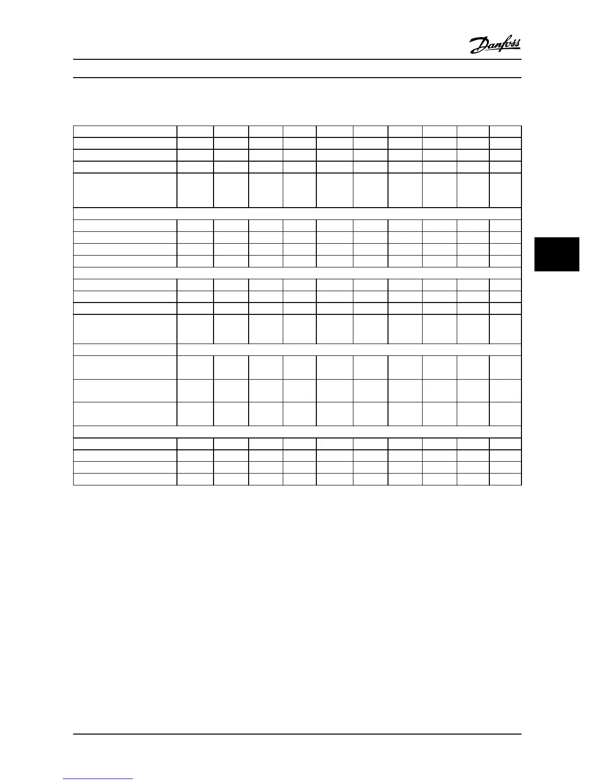
6.1.2 3x380–480 V AC
Adjustable frequency drive PK37 PK75 P1K5 P2K2 P3K0 P4K0 P5K5 P7K5 P11K P15K
Typical shaft output [kW] 0.37 0.75 1.5 2.2 3.0 4.0 5.5 7.5 11.0 15.0
Typical shaft output [HP] 0.5 1.0 2.0 3.0 4.0 5.0 7.5 10.0 15.0 20.0
IP20 frame H1 H1 H1 H2 H2 H2 H3 H3 H4 H4
Maximum cable size in
terminals (line power, motor)
[mm
2
(AWG)]
4 (10) 4 (10) 4 (10) 4 (10) 4 (10) 4 (10) 4 (10) 4 (10) 16 (6) 16 (6)
Output current - 40 °C (104 °F) ambient temperature
Continuous (3x380–440 V) [A] 1.2 2.2 3.7 5.3 7.2 9.0 12.0 15.5 23.0 31.0
Intermittent (3x380–440 V) [A] 1.3 2.4 4.1 5.8 7.9 9.9 13.2 17.1 25.3 34.0
Continuous (3x441–480 V) [A] 1.1 2.1 3.4 4.8 6.3 8.2 11.0 14.0 21.0 27.0
Intermittent (3x441–480 V) [A] 1.2 2.3 3.7 5.3 6.9 9.0 12.1 15.4 23.1 29.7
Maximum input current
Continuous (3x380–440 V) [A] 1.2 2.1 3.5 4.7 6.3 8.3 11.2 15.1 22.1 29.9
Intermittent (3x380–440 V) [A] 1.3 2.3 3.9 5.2 6.9 9.1 12.3 16.6 24.3 32.9
Continuous (3x441–480 V) [A] 1.0 1.8 2.9 3.9 5.3 6.8 9.4 12.6 18.4 24.7
Intermittent (3x441–480 V) [A] 1.1 2.0 3.2 4.3 5.8 7.5 10.3 13.9 20.2 27.2
Maximum electrical fuses
See chapter 3.2.4 Fuses and Circuit Breakers
Estimated power loss [W],
best case/typical
1)
13/15 16/21 46/57 46/58 66/83 95/118 104/131 159/198 248/274 353/379
Weight enclosure IP20 [kg (lb)] 2.0 (4.4) 2.0 (4.4) 2.1 (4.6) 3.3 (7.3) 3.3 (7.3) 3.4 (7.5) 4.3 (9.5) 4.5 (9.9) 7.9
(17.4)
7.9
(17.4)
Efficiency [%],
best case/typical
2)
97.8/97.3 98.0/97.6 97.7/97.2 98.3/97.9 98.2/97.8 98.0/97.6 98.4/98.0 98.2/97.8 98.1/97.
9
98.0/97.
8
Output current - 50 °C (122 °F) ambient temperature
Continuous (3x380–440 V) [A] 1.04 1.93 3.7 4.85 6.3 8.4 10.9 14.0 20.9 28.0
Intermittent (3x380–440 V) [A] 1.1 2.1 4.07 5.4 6.9 9.2 12.0 15.4 23.0 30.8
Continuous (3x441–480 V) [A] 1.0 1.8 3.4 4.4 5.5 7.5 10.0 12.6 19.1 24.0
Intermittent (3x441–480 V) [A] 1.1 2.0 3.7 4.8 6.1 8.3 11.0 13.9 21.0 26.4
Table 6.2 3x380–480 V AC, 0.37–15 kW (0.5–20 HP), Enclosure Type H1–H4
1) Applies for dimensioning of adjustable frequency drive cooling. If the switching frequency is higher than the default setting, the power losses
may increase. LCP and typical control card power consumptions are included. For power loss data according to EN 50598-2, refer to
www.danfoss.com/vltenergyefficiency.
2) Efficiency measured at nominal current. For energy efficiency class, see chapter 6.4.13 Ambient Conditions. For part load losses, see
www.danfoss.com/vltenergyefficiency.
Specifications Quick Guide
MG18A622 Danfoss A/S © 08/2014 All rights reserved. 47
6 6
 Loading...


