130BC506.10
Setup 1
A
B
C
D
5
12
13 14 15
10
11
10
9
6
7
8
4
1
2
3
Menu
Status
Quick
Menu
Main
Menu
Hand
On
O
Reset
Auto
On
Back
OK
On
Warn
Alarm
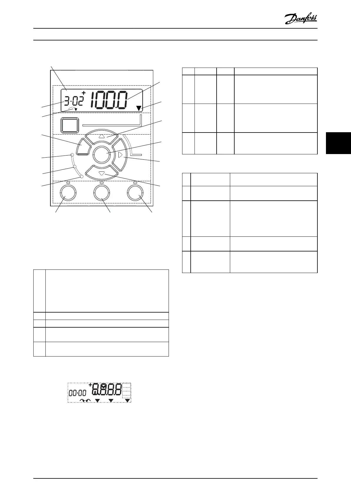
Illustration 5.1 View of the NLCP
A. Numeric display
The LCD display is backlit with 1 numeric line. All data is
shown in the NLCP.
1
The set-up number shows the active set-up and the edit
set-up. If the same set-up acts as both active and edit set-
up, only that set-up number is shown (factory setting).
When active and edit set-up dier, both numbers are
shown in the display (for example set-up 12). The number
ashing indicates the edit set-up.
2 Parameter number.
3 Parameter value.
4
Motor direction is shown at the bottom left of the display.
A small arrow indicates the direction.
5
The triangle indicates whether the LCP is in Status, Quick
Menu, or Main Menu.
Table 5.1 Legend to Illustration 5.1, Section A
130BD135.10
Setup 1234
INDEX
AHP
VkW
srpm
Hz%
n2n1
n3
p5 p4
p3 p2 p1
Illustration 5.2 Display Information
B. Menu key
To select between Status, Quick Menu, or Main Menu,
press [Menu].
C. Indicator lights (LEDs) and navigation keys
Indicator Light Function
6 On Green
ON turns on when the frequency
converter receives power from the
mains voltage, a DC bus terminal, or a
24 V external supply.
7 Warn Yellow
When warning conditions are met, the
yellow WARN LED turns on, and text
appears in the display area identifying
the problem.
8 Alarm Red
A fault condition causes the red alarm
LED to ash and an alarm text is
shown.
Table 5.2 Legend to Illustration 5.1, Indicator Lights (LEDs)
Key Function
9 [Back]
For moving to the previous step or layer
in the navigation structure.
10
[
▲
] [
▼
]
For switching between parameter groups,
parameters, and within parameters, or
increasing/decreasing parameter values.
Arrows can also be used for setting local
reference.
11 [OK]
Press to access parameter groups or to
enable a selection.
12
[►]
Press to move from left to right within
the parameter value to change each digit
individually.
Table 5.3 Legend to Illustration 5.1, Navigation Keys
Commissioning Operating Guide
MG07A402 Danfoss A/S © 10/2017 All rights reserved. 25
5 5
 Loading...


