4.2 Process Data
Use the process data part of the PPO to control and
monitor the frequency converter via the PROFIBUS.
4.2.1 Process Control Data
Process control data (PCD) is the process data sent from
the PLC to the frequency converter.
Master/slave
1 2 3 ....... 10
CTW MRV PCD ....... PCD
PCD write
Table 4.1 Process Control Data
PCD 1 contains a 16-bit control word, and each bit controls
a
specic function of the frequency converter, see
chapter 4.3 Control Prole.
PCD 2 contains a 16-bit speed setpoint in percentage
format. See chapter 4.2.3 Reference Handling.
The settings in parameter 9-15 PCD Write Conguration and
parameter 9-16 PCD Read Conguration dene the content
of PCD 3 to PCD 10.
4.2.2 Process Status Data
Process status data is the process data sent from the
frequency converter and contains information about the
current state.
Slave/master
1 2 3 ...... 10
STW MAV PCD ...... PCD
PCD read
Table 4.2 Process Status Data
PCD 1 contains a 16-bit status word, and each bit contains
information regarding a possible state of the frequency
converter.
PCD 2 contains per default the value of the current speed
of the frequency converter in percentage format (see
chapter 4.2.3 Reference Handling). PCD 2 can be congured
to contain other process signals.
The settings in parameter 9-16 PCD Read Conguration
dene the content of PCD 3 to PCD 10.
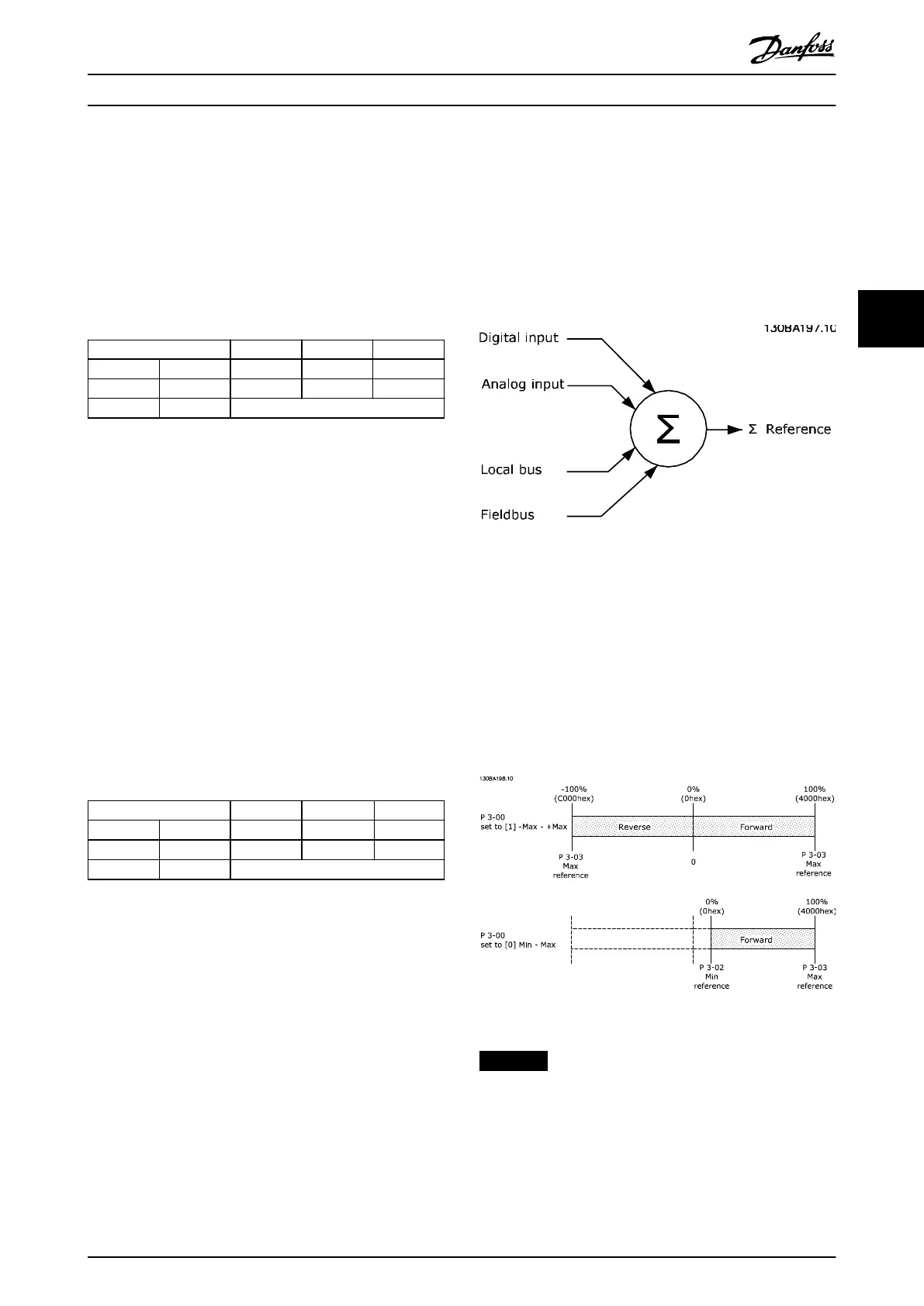
4.2.3 Reference Handling
The reference handling is an advanced mechanism that
sums up references from dierent sources, as shown in
Illustration 4.2.
For more information on reference handling, refer to the
design guide of the relevant frequency converter.
Illustration 4.2 Reference
The reference, or speed setpoint, is sent via PROFIBUS and
is always transmitted to the frequency converter in
percentage format as integers shown in hexadecimal (0–
4000 hex).
The reference (MRV) and feedback (MAV) are always scaled
equally. The setting of parameter 3-00 Reference Range
determines the scaling of the reference and feedback
(MAV), see Illustration 4.3.
Illustration 4.3 Reference (MRV) and Feedback (MAV), Scaled
NOTICE
When parameter 3-00 Reference Range is set to [0] Min -
Max, a negative reference is handled as 0%.
The actual output of the frequency converter is limited by
the speed limit parameters Motor Low/High Speed Limit
[RPM/Hz] in parameter 4-11 Motor Speed Low Limit [RPM] to
parameter 4-14 Motor Speed High Limit [Hz].
Control Programming Guide
MG37G202 Danfoss A/S © 01/2016 All rights reserved. 15
4 4