The nal speed limit is set in parameter 4-19 Max Output
Frequency.
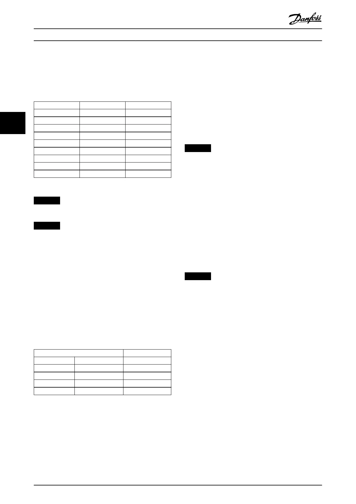
Table 4.3 lists the reference (MRV) and the feedback (MAV)
formats.
MRV/MAV Integer in hex Integer in decimal
100% 4000 16384
75% 3000 12288
50% 2000 8192
25% 1000 4096
0% 0 0
-25% F000 -4096
-50% E000 -8192
-75% D000 -12288
-100% C000 -16384
Table 4.3 Reference/Feedback (MRV/MAV) Format
NOTICE
Negative numbers are formed as complement of 2.
NOTICE
The data type for MRV and MAV is an N2 16-bit
standardized value, expressing a range from -200% to
+200% (8001 to 7FFF).
Example
The following settings determine the speed, as shown in
Table 4.4:
•
Parameter 1-00 Conguration Mode set to [0]
Speed open loop.
•
Parameter 3-00 Reference Range set to [0] Min-Max.
•
Parameter 3-02 Minimum Reference set to 100
RPM.
•
Parameter 3-03 Maximum Reference set to 3000
RPM.
MRV/MAV Actual speed [RPM]
0% 0 hex 100
25% 1000 hex 825
50% 2000 hex 1550
75% 3000 hex 2275
100% 4000 hex 3000
Table 4.4 Actual Speed for MRV/MAV
4.2.4 Process Control Operation
In process control operation, parameter 1-00 Conguration
Mode is set to [3] Process.
The reference range in parameter 3-00 Reference Range is
always [0] Min - Max.
•
MRV is the process setpoint.
•
MAV expresses the actual process feedback (range
±200%).
4.2.5 Inuence of the Digital Input
Terminals on FC Control Mode
In parameter 8-50 Coasting Select to parameter 8-56 Preset
Reference Select, set the inuence of the digital input
terminals on the control of the frequency converter.
NOTICE
The setting of parameter 8-01 Control Site overrules the
settings in parameter 8-50 Coasting Select to
parameter 8-56 Preset Reference Select. The setting of
terminal 37 coast stop (safe) overrules any other
parameter.
Program each of the digital input signals to logic AND,
logic OR, or to have no relation to the corresponding bit in
the control word. In this way, the following signal sources
initiate a specic control command, for example stop/
coast:
•
Fieldbus only.
•
Fieldbus AND digital input.
•
Either eldbus OR digital input terminal.
NOTICE
To control the frequency converter via PROFIBUS, set
parameter 8-50 Coasting Select to either [1] Bus or [2]
Logic AND. Then set parameter 8-01 Control Site to [0]
Digital and ctrl.word or [2] Controlword only.
For more detailed information and examples of logical
relationship options, see chapter 8 Troubleshooting.
4.3
Control Prole
Control the frequency converter according to:
•
The PROFIdrive prole, see chapter 4.4 PROFIdrive
Control Prole, or
•
The Danfoss FC control, see chapter 4.5 Danfoss
FC Control Prole.
Select the control prole in parameter 8-10 Control Word
Prole. The choice of prole aects the control word and
status word only.
Chapter 4.4 PROFIdrive Control Prole and
chapter 4.5 Danfoss FC Control Prole provide a detailed
description of control and status data.
Control
VLT
®
PROFIBUS DP MCA 101
16 Danfoss A/S © 01/2016 All rights reserved. MG37G202
44

 Loading...


