4.5 Danfoss FC Control Prole
4.5.1 Control Word According to FC Prole
(CTW)
To select Danfoss FC protocol in the control word, set
parameter 8-10 Control Word Prole to [0] Frequency
converter prole. Use the control word to send commands
from a master (PLC or PC) to a slave (frequency converter).
Bit Bit value=0 Bit value=1
00 Reference value External selection lsb
01 Reference value External selection msb
02 DC brake Ramp
03 Coasting No coasting
04 Quick stop Ramp
05 Hold output frequency Use ramp
06 Ramp stop Start
07 No function Reset
08 No function Jog
09 Ramp 1 Ramp 2
10 Data invalid Data valid
11 No function Relay 01 active
12 No function Relay 04 active
13 Parameter set-up Selection lsb
14 Parameter set-up Selection msb
15 No function Reverse
Table 4.8 Bit Values for FC Control Word
Explanation of the control bits
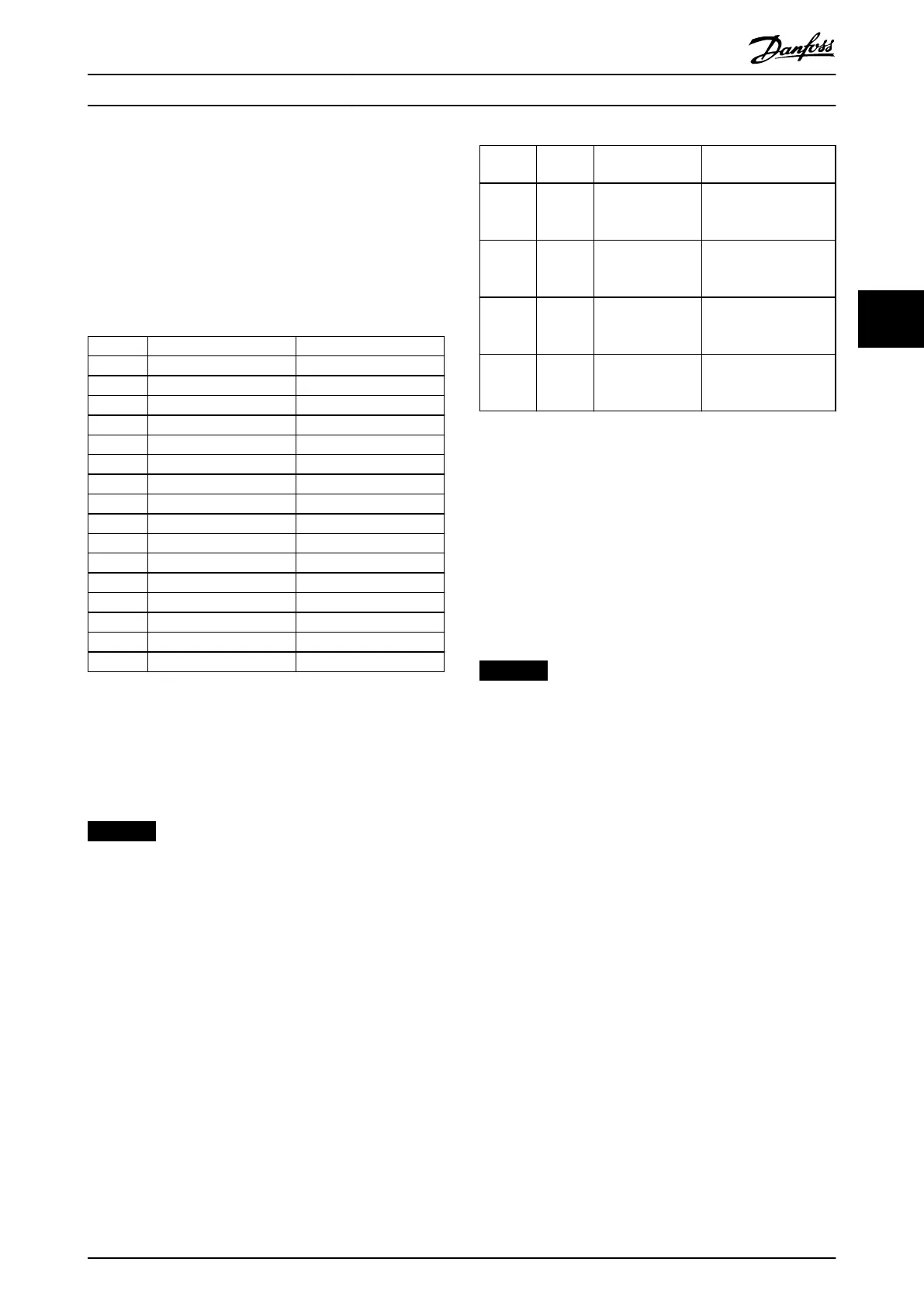
Bits 00/01 reference value
Use bits 00 and 01 to select between the 4 reference
values, which are pre-programmed in parameter 3-10 Preset
Reference according to Table 4.9.
NOTICE
In parameter 8-56 Preset Reference Select, a selection is
made to dene how bit 00/01 gates with the
corresponding function on the digital inputs.
Bit 01 Bit 00 Programmed
reference value
Parameter
0 0 1 [0]
Parameter 3-10 Preset
Reference
0 1 2 [1]
Parameter 3-10 Preset
Reference
1 0 3 [2]
Parameter 3-10 Preset
Reference
1 1 4 [3]
Parameter 3-10 Preset
Reference
Table 4.9 Programmed Reference Values for Bits
Bit 02, DC brake
Bit 02=0 leads to DC braking and stop. Braking current and
duration are set in parameter 2-01 DC Brake Current and
parameter 2-02 DC Braking Time.
Bit 02=1 leads to ramping.
Bit 03, coasting
Bit 03=0 causes the frequency converter immediately to
coast the motor to a standstill.
Bit 03=1 enables the frequency converter to start the
motor if the other starting conditions have been fullled.
NOTICE
In parameter 8-50 Coasting Select, a selection is made to
dene how bit 03 gates with the corresponding function
on a digital input.
Bit 04, quick stop
Bit 04=0 quick stops the frequency converter and ramps
the motor speed down to stop via parameter 3-81 Quick
Stop Ramp Time.
Bit 04=1 makes the frequency converter ramp the motor
speed down to stop via parameter 3-42 Ramp 1 Ramp
Down Time or parameter 3-52 Ramp 2 Ramp Down Time.
Bit 05, hold output frequency
Bit 05=0 freezes the present output frequency (in Hz). The
frozen output frequency can only be changed with the
digital inputs (parameter 5-10 Terminal 18 Digital Input to
parameter 5-15 Terminal 33 Digital Input) programmed to
[21] Speed up and [22] Speed down.
Bit 05=1 uses ramp.
Control Programming Guide
MG37G202 Danfoss A/S © 01/2016 All rights reserved. 21
4 4

 Loading...


