Program the frequency converter as in Table 7.2:
Parameter Setting
Parameter 4-10 Motor Speed Direction [2] Both directions
Parameter 5-10 Terminal 18 Digital Input [0] No operation
Parameter 5-11 Terminal 19 Digital Input [10] Reversing
Parameter 5-40 Function Relay [36/37] Control word bit 11/12
Parameter 8-03 Control Word Timeout Time 1 s
Parameter 8-04 Control Word Timeout Function [2] Stop
Parameter 8-10 Control Word Prole [0] FC Prole
Parameter 8-50 Coasting Select [1] Bus
Parameter 8-51 Quick Stop Select [1] Bus
Parameter 8-52 DC Brake Select [1] Bus
Parameter 8-53 Start Select [1] Bus
Parameter 8-54 Reversing Select [2] Logic AND
Parameter 8-55 Set-up Select [1] Bus
Parameter 8-56 Preset Reference Select [1] Bus
Parameter 9-16 PCD Read Conguration [2] Sub index parameter 16-16 Torque [Nm]
[3] Sub index parameter 16-60 Digital Input
Parameter 9-18 Node Address Set the address
Table 7.2 Parameter Settings
7.2
Example 2: Control Word Telegram using PPO Type
This example shows how the control word telegram relates to the PLC and the frequency converter, using FC control prole.
The PLC sends the control word telegram to the frequency converter. In the example, PPO Type 3 demonstrates the full
range of modules. All the values shown are arbitrary and are provided for demonstration purposes only.
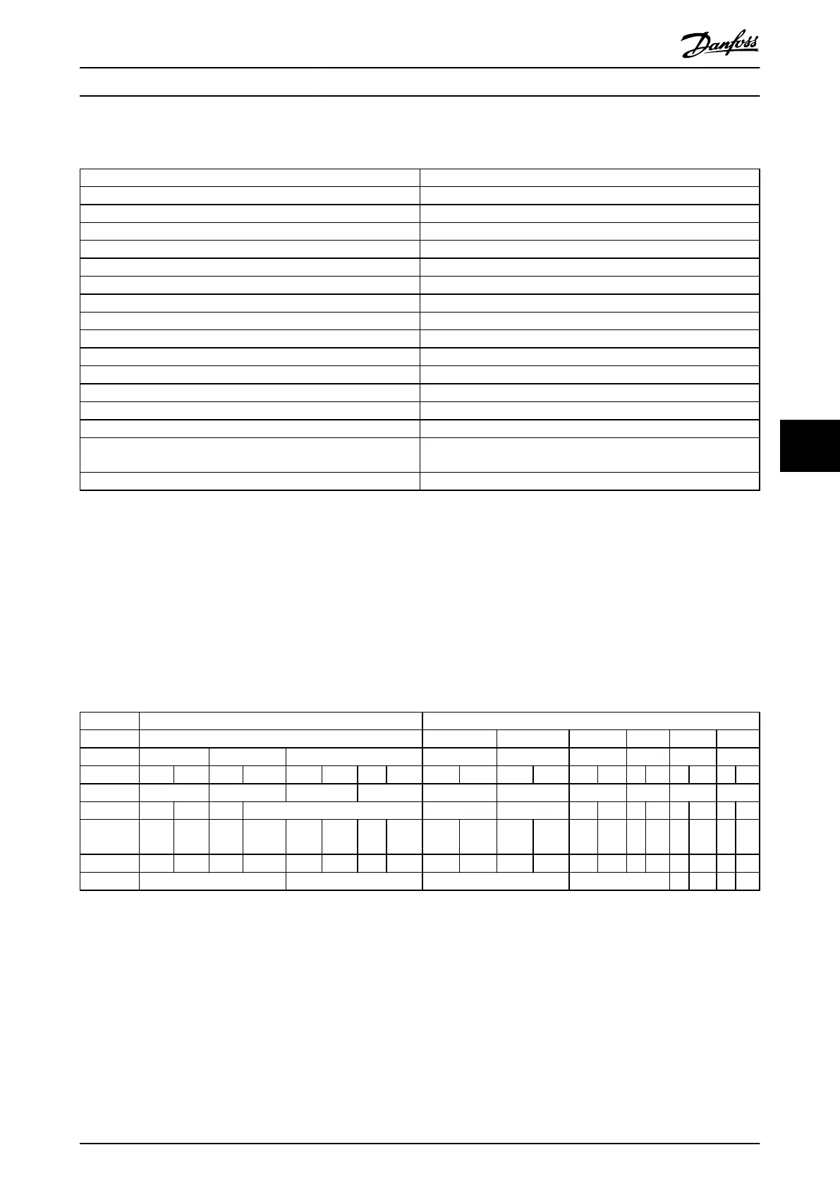
Table 7.3 indicates the bits contained within the control word, and how they are presented as process data in PPO type 3 for
this example.
PCV PCD
1 2 3 4 5 6
PCA IND PVA CTW MRV PCD PCD PCD PCD
04 7C 20 00
PQW 256 258 260 262 264 266 268 270 272 274
master slave CTW MRV
Bit
number
15 14 13 12 11 10 9 8 7 6 5 4 3 2 1 0
0 0 0 0 0 1 0 0 0 1 1 1 1 1 0 0
0 4 7 C
Table 7.3 Example: Control Word Telegram using PPO Type
Application Examples Programming Guide
MG37G202 Danfoss A/S © 01/2016 All rights reserved. 49
7 7

 Loading...


