4.4.3 PROFIdrive State Transition Diagram
In the PROFIdrive control prole, the control bits:
•
0–3 perform the basic start-up/power-down functions.
•
4–15 perform application-oriented control.
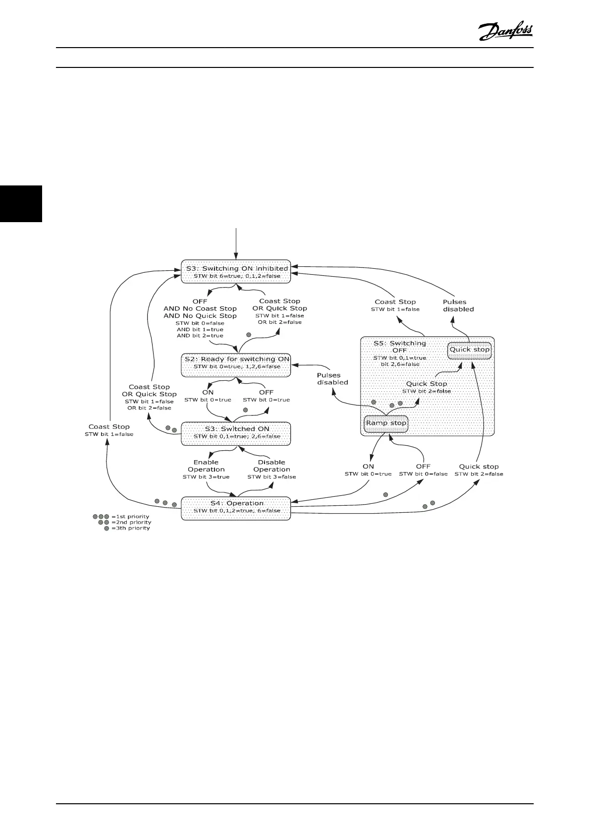
Illustration 4.4 shows the basic state transition diagram, where control bits 0–3 control the transitions, and the corresponding
status bit indicates the actual state. The black bullets indicate the priority of the control signals, where fewer bullets indicate
lower priority, and more bullets indicate higher priority.
Illustration 4.4 PROFIdrive State Transition Diagram
Control
VLT
®
PROFIBUS DP MCA 101
20 Danfoss A/S © 01/2016 All rights reserved. MG37G202
44

 Loading...


