Instruction Manual DS2
5.3. Transition detection (number of transitions)
The transition detection counts the number of transitions in the detection area. The number of
transition increases each time that an object is detected inside the detection area and decreases each
time the objects remain outside (transition light->dark).
5.4. Notes on functioning mode
The DS2 light grids can configure the beam reference status, specifically selecting it from the user
interface. The default selection is “dark beam”, but the operator can select the complementary
situation i.e. “light beam”.
Not all the functions can be selected using dip-switches. Please refer to the following tables to
discover the local programmability of the device.
The 0-10 V analogue output, supplies limited information if compared to the information that can be
obtained from the serial output; some functions are significant only if obtained in a serial ambient.
The analogue voltage value is supplied, in these cases, without direct correspondence, as
indicated in the tables found in page 12, 24 and 26.
The formula to determine the voltage is obtained with the following syntax:
V
OUT
=V
RES
* N
BEAM
[xxx ; yyy]
Where V
OUT
= voltage value of the analogue output
V
RES
= 10V/total n° of beams of the device = Voltage value corresponding to the
minimum resolution (obtained obscuring only one beam)
N
BEAM
[xxx ; yyy] = Number of beams belonging to the group [XY]
(i.e. between “xxx” beam and “yyy” beam)
Please note that the longer DS2 is, the less conditioning is V
RES.
In the worst case V
RES
= 43 mV !
(using the DS2 165 model)
The first reference beam to select, by using only dip-switches, can be the one closest beam
(default reference) or the one furthest away from the connector, located at the opposite side of the
unit where the analogue voltage is at the minimum level (positive ramp 0-10 V) or maximum
(negative ramp 10-0V) in correspondence of the obscuring of the default reference beam.
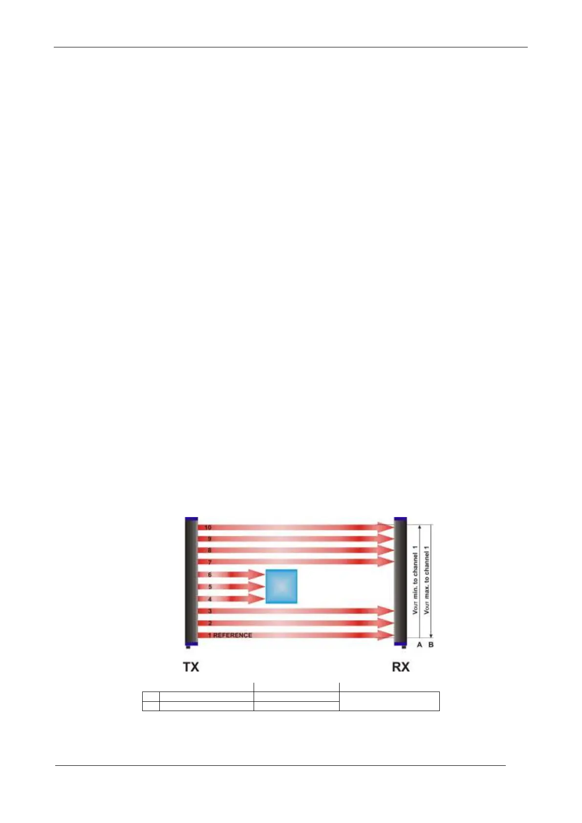
Fig. 10 can be used as an example, considering a device with 10 beams, where the obscuring of
one beam corresponds to the V
OUT
variation of 1V (V
RES
= 1V). At last beam obscuring, the V
OUT
reaches 10 V full scale.
If the first beam is selected as the reference, the V
OUT
in the example is = 6 V. If the last beam is
selected as the reference, the V
OUT
in the example is = 7 V (B).
Fig. 7
The information can be obtained from the serial output, setting the top beam and bottom beam
measurement modes.
 Loading...