Instruction Manual DS2
6.2.3. Graphic user interface
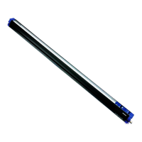
The following window will be visualised at program initialisation:
Fig. 12
Two important areas are distinguished: the data control area on the left (graph representing light
grid with scanning area, Teach-in status indicated on a measurement bar, a panel with luminous
indicators and dip-switch status, various digital indicators for measurement visualisation and a
communication status bar). The function selection area is on the right side.
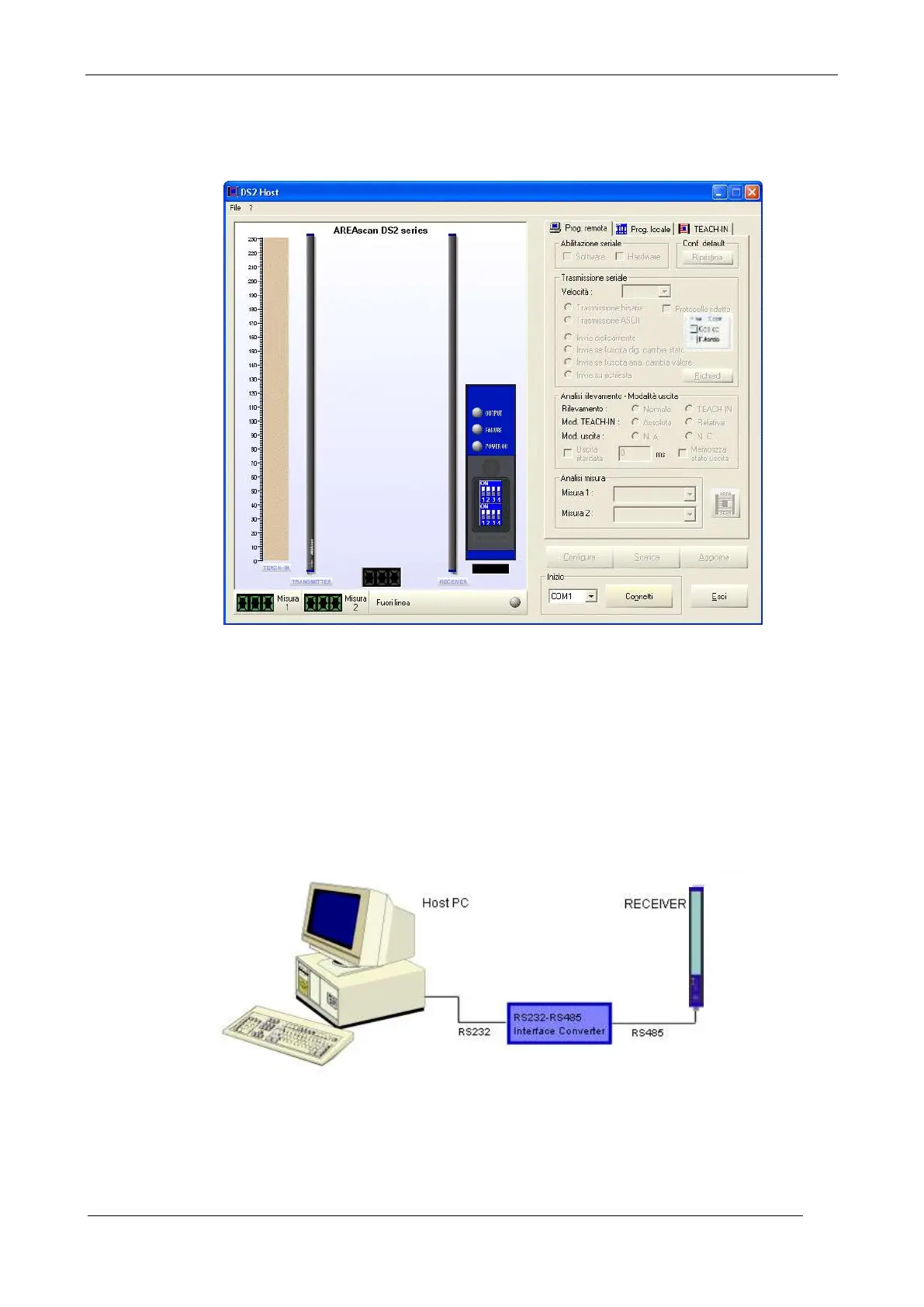
6.2.4. Connection with AREAscan
TM
DS2 series
As mentioned, the DS2 light grid has a RS485 serial communication line (half duplex).
As far as the PC is concerned, a RS232/RS485 serial adapter is necessary in order to communicate
with the light grid receiver. The program controls the receipt/transmission on the RS485 line using
the RTS line present on the RS232 connector. The adapter has to support this characteristic.
Fig. 13
 Loading...