PRESENCE SENSOR POSITIONING
INSTALLATION GUIDE 7
PRESENCE SENSOR POSITIONING
The STS320 system comes with a pair of photocells that can be used to detect the pres-
ence of the tire on the conveyor and trigger the beginning and the end of the reading
phase. When used, they mu
st be positioned and mounted at the conveyor belt level
depending on the size of the tires that must be handled.
Position the presence sensors according to the following procedure:
1. Retrieve the size of the
minimum tire height (FOV
v
) at the minimum tire width
(W
min
).
2. Determine the field of view along the conveyor direction (FOV
v
) at the maximum
distance. See the table below.
STS320-00x 260 mm
STS320-01x 211 mm
STS320-10x 305 mm
STS320-11x 214 mm
STS320-20x 247 mm
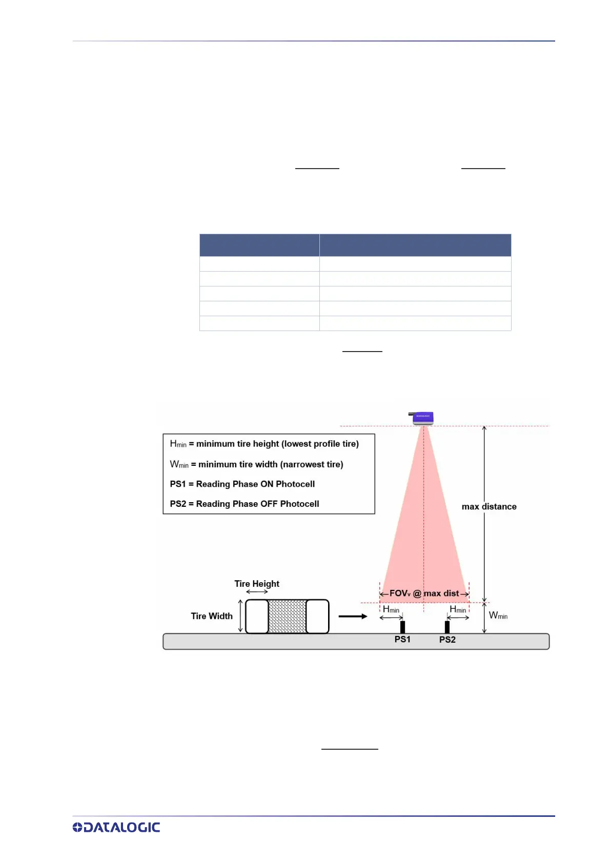
3. If the minimum tire height (H
min
) is less than the FOV
v
/2 at the maximum distance,
then both Reading Phase ON and Reading Phase OFF presence sensors are
required and they must be mounted at the H
min
distance from the edges of the
vertical FOV as shown in the figure below:
Figure 7 - Top reading station with two presence sensors
In some cases the system can work with only one photocell.
If the minimum tire height (H
min
) is greater than the FOV
v
/2 at the maximum distance,
then only a single presence sensor is required and it must be mounted at the mid point
of the field of view as shown in Figure 8:
Model Typical FOV @ Max. Distance
 Loading...