DIGITAL INPUTS
INSTALLATION GUIDE 11
DIGITAL INPUTS
There are two optocoupled polarity insensitive inputs available on the reader: Input 1
(External Trigger) and Input 2, a generic input:
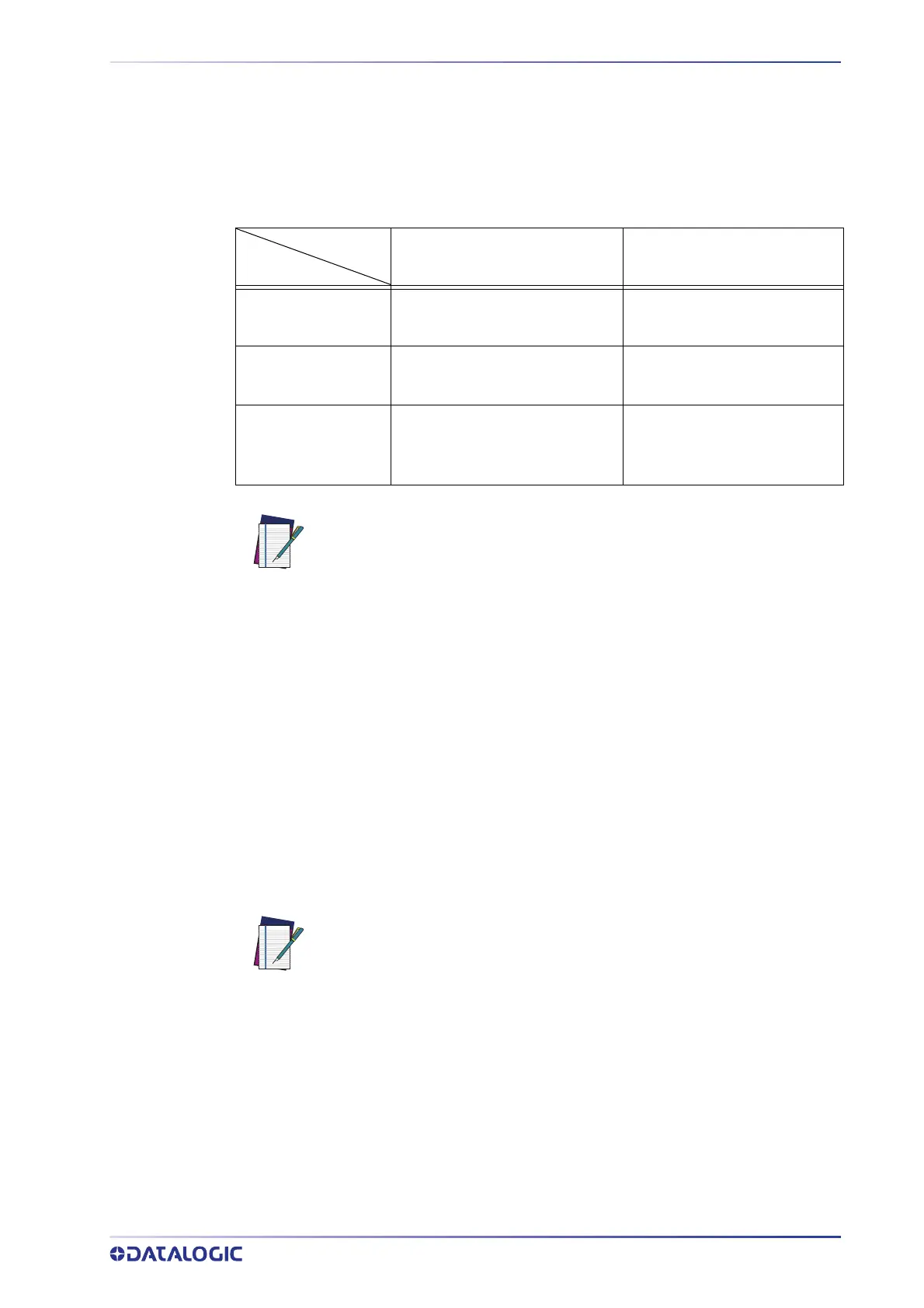
These inputs can be used to control (start/stop) the reading phase:
Parameter
Source
Reading Phase ON Input Reading Phase OFF Input
Single Presence
Sen
sor
External Trigger Leading Edge External Trigger Trailing Edge
Two Presence
Sensors
External Trigger Leading Edge Input 2 Leading Edge
PLC Digital Output
External Trigger Leading Edge
or
Input 2 Leading Edge
External Trigger Trailing Edge
or
Input 2 Trailing Edge
NOTE
The electrical features of both inputs are:
V
AB
= 30 Vdc max.
I
IN
= 10 mA (reader) + 12 mA (CBX) max.
The active state of these inputs is selected in software.
An anti-disturbance filter is implemented in software on both inputs so that the mini-
mum pulse duration is ≅ 0.5 millisec
onds. This value can be increased through software.
These inputs are optocoupled and can be driven by PNP type commands.
NOTE
Alternatively, host communication output commands (Serial or Fieldbus)
can be used to control the reading phase. See the DL.CODE Configuration
Parameters Help On Line for details.
Polarity insensitive inputs assure full functionality even if pins A and B
are exchanged.
 Loading...