ELECTRICAL CONNECTIONS
14 STS320
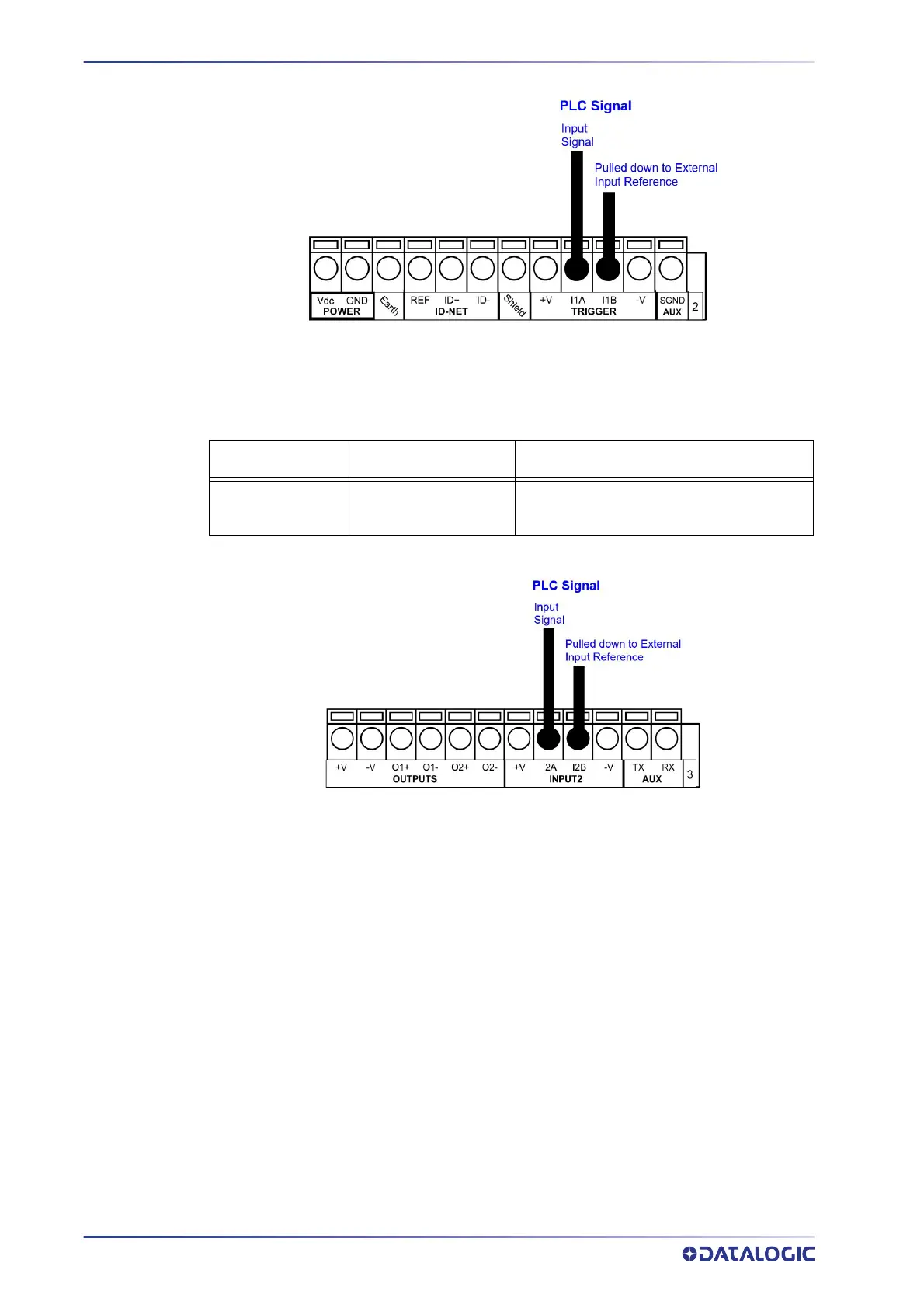
Figure 14 - External Trigger Connected to PLC
The yellow Trigger LED on the reader is on when the active state of the External Trigger
corresponds to ON.
PLC Signal CBX500 Row 3 Function
Input
Reference
I2A
I2B
Input 2 A (polarity insensitive)
Input 2 B (polarity insensitive)
Figure 15 - Input 2 Connected to PLC
DIGITAL OUTPUTS
Three short-circuit protected outputs are available that can be configured as NPN, PNP
and PP. Using a CBX connection box, the first two outputs are opto-coupled. The mean-
ing of the three outputs can be defined by the user. They are typically used to signal the
d
ata collection result. They are also available to the Host (either serial or Fieldbus) to be
driven independently.
The electrical features of the two outputs are the following:
V
OUT
(I
LOAD
= 0 mA) max. 24 Vdc
V
OUT
(I
LOAD
= 100 mA) max. 3 Vdc
I
LOAD
max. 100 mA
By default, Output 1 is associated with the P
artial Read and No Read events, which acti-
vates when the code(s) signaled by the external trigger are not decoded, and Output 2 is
associat
ed with the Complete Read event, which activates when all the selected codes
are correctly decoded. The output signals are fully programmable through DL.CODE.
 Loading...