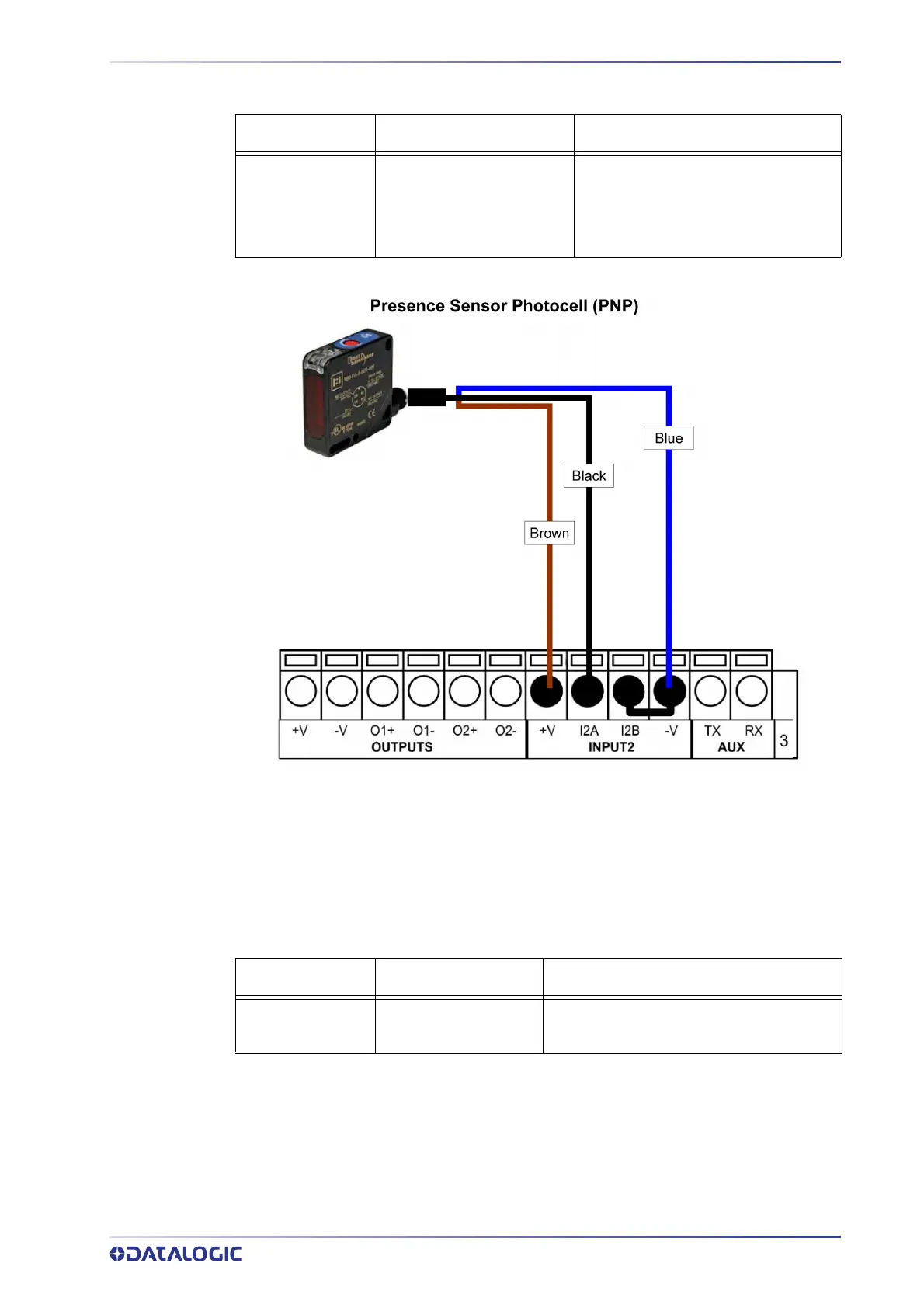
Sensor 2 CBX500 Row 2 Function
brown
black
blue
+V
I2A
I2B
-V (bridge to I2B)
Power Source - External Trigger
Input 2 A (polarity insensitive)
Input 2 B (polarity insensitive)
Power Reference - Inputs
DIGITAL INPUTS
INSTALLATION GUIDE 13
Figure 13 - Presence Sensor Connected to Input 2
Input Connections from PLC
Alternatively, the reading system can be controlled by a digital output of a PLC. For this
purpose, connect the switched signal and the appropriate reference level as shown in
the figures below.
PLC Signal CBX500 Row 2 Function
Input
Reference
I1A
I1B
External Trigger A (polarity insensitive)
External Trigger B (polarity insensitive)
 Loading...