I
Solar sensor probe.
O
Buffer tank.
P
Connect the solar station to the solar collectors.
a
Solar sensor probe.
Settings to be made for this type of installation
Parameters Access Settings to be made See
INSTALLATION
Installer level
#SYSTEM Menu
EXTENDED
¼ "Displaying the parameters in extended mode", page 33
I.SYST
(1)
Installer level
#SYSTEM Menu
BUFFER TANK
¼ "Setting the parameters specific to the installation", page
33
(1) The parameter is only displayed if INSTALLATION parameter is set to EXTENDED
The DHW part is maintained at the DHW set point by the
boiler.
The heating zone is maintained at the set temperature
calculated according to the outside temperature. The zone
is reheated when the heating buffer temperature sensor
falls -6°C below the calculated set temperature. Reheating
in the heating zone stops when the heating buffer
temperature rises above the calculated set temperature.
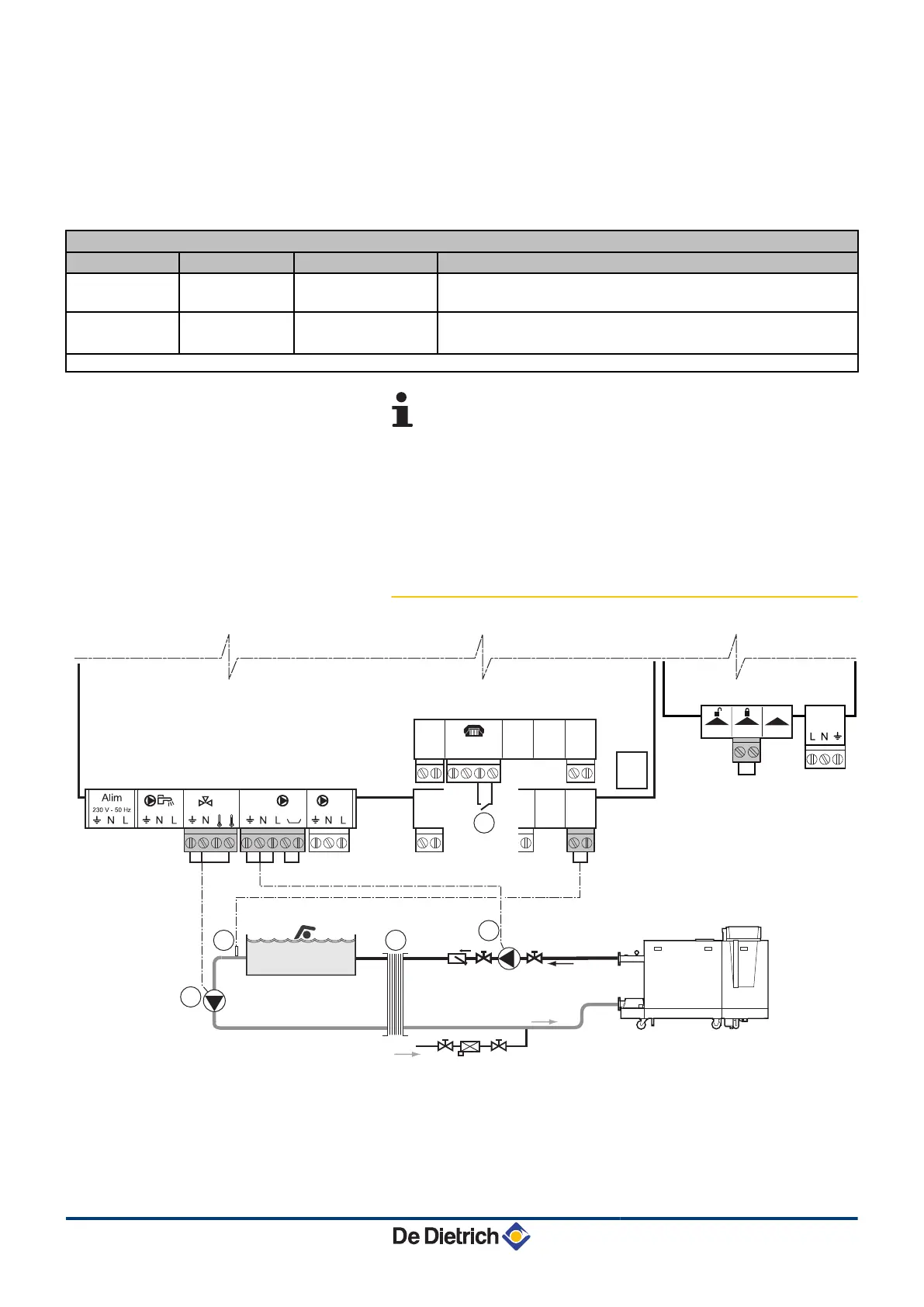
4.4.6. Pool connection
L000163-D
1
3
5
2
TS + B AB
0-10V
S AMB C
4 3 2 1 2 1
+ -
S AMB B
2 1
S AMB A
2 1
S SYST + TA -
S ECS S EXT S DEP C
2 12 12 12 1 2 1
S DEP B
2 1
SCU
4
On/off
OT
BL
RL
PCU
PUMP
A
Connect the secondary swimming pool pump.
Z
Connect the swimming pool sensor.
E
Plate heat exchanger.
4. Installation Diematic iSystem For C 330 / C 630 ECO
21
31082018 - 7600691-001-06
 Loading...