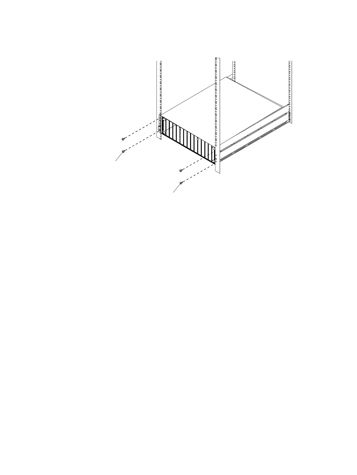
Figure 33 Securing enclosure to the front of the cabinet
Transferring components from the faulted DAE to the replacement DAE
Use the procedures in this section to transfer each power/cooling module, link control cards
(LCCs), disk, and disk filler module from the faulted DAE to the corresponding locations in the
replacement DAE.
To help ensure the correct placement in the enclosure:
l
Transfer one component at a time.
l
When transferring a power/cooling module or LCC:
Always move a component from position A (faulted) to position A (replacement), or B to B; do
not move A to B or B to A.
n
Move components from position A of the faulted DAE to position A of the replacement
DAE.
n
Move components from position B of the faulted DAE to position B of the replacement
DAE.
l
Transfer each disk and disk filler module to the SAME SLOT LOCATION that it occupied in
faulted DAE.
Removing a power/cooling module
About this task
Refer Figure 34 on page 44 to while performing the procedure that followins.
Procedure
1.
Turn the captive screw counterclockwise to release the power/cooling module.
2. Remove the module from the enclosure.
Removing and replacing FRUs
Dell EMC ES40 Expansion Shelf Guide Field Replacement Unit Guide 43
 Loading...