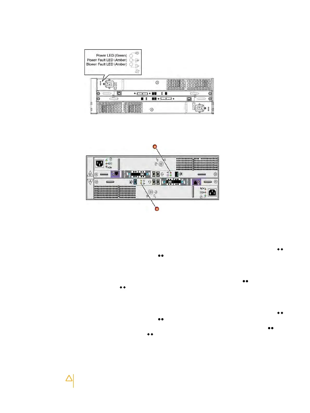
Figure 43 Enclosure status LEDs
2. Verify that the shelf fault LED is not lit (Figure 44 on page 51).
Figure 44 Enclosure fault LED
Connecting the back-end bus to the shelf
Procedure
1. On controller A in the previous enclosure on the bus, locate the cable plugged into the
port and plug its free end into the port on controller A in the replacement enclosure.
The enclosure immediately before an enclosure on the same back-end bus is called the
previous enclosure.
2. On controller A in the next enclosure, locate the cable plugged into the port and plug its
free end into the port on controller A in the replacement enclosure.
The enclosure immediately after an enclosure on the same back-end bus is called the next
enclosure.
3. On controller B in the previous enclosure on the bus, locate the cable plugged into the
port and plug its free end into the port on controller B in the replacement enclosure.
4.
On controller B in the next enclosure on the bus, locate the cable plugged into the
port
and plug its free end into the port on controller B in the replacement enclosure.
5.
Verify that the Bus ID LED displays the expected value.
Installing and locking the front bezel
Before you begin
CAUTION You must remove the protective plastic strip from the front of the bezel before
placing the system into operation. Failure to do this will cause the system to overheat.
Removing and replacing FRUs
Dell EMC ES40 Expansion Shelf Guide Field Replacement Unit Guide 51
 Loading...