Connecting power to the replacement enclosure
About this task
Use the procedure that follows to connect the AC power cord to each power/cooling module.
Refer to Figure 42 on page 50while performing the procedure.
Procedure
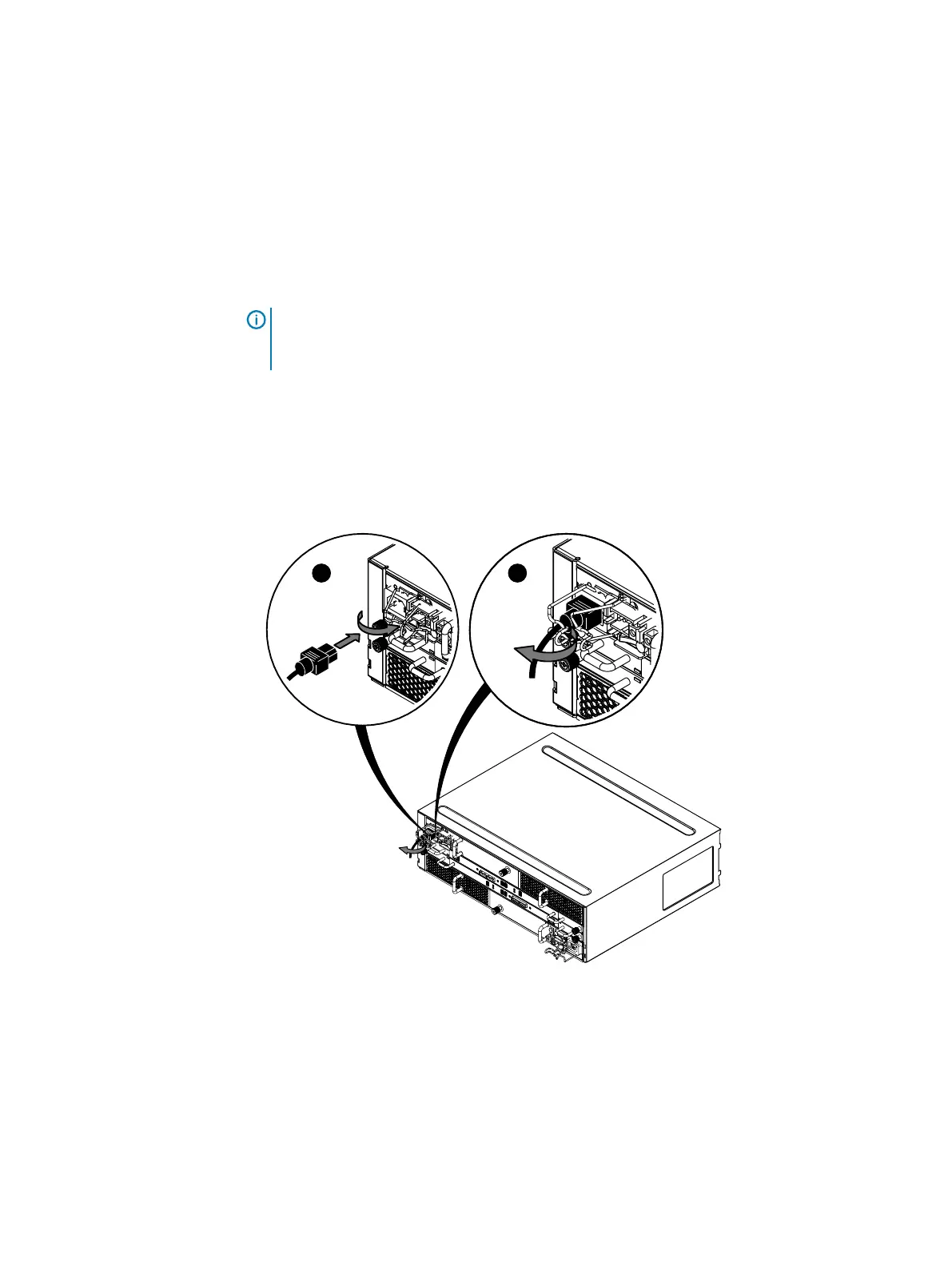
1. Plug in the AC power cord.
NOTICE Do not connection a power/cooling module in an optional power/cooling
module to an SPS. Only connect a power/cooling module in enclosure 0 on bus 0, which
contains the system (vault) disks, to the SPS.
As soon as the enclosure is connected to a live power source, it powers up and its lights
begin blinking.
2. Secure the power cord with the retention bail at the connector.
The bail prevents the power cord from pulling out of the connector.
Figure 42 Plugging in and securing an AC power cord
Verifying shelf status
Procedure
1.
Verify that the shelf power LED is lit and that the power fault and blower fault LEDs are not
lit (Figure 43 on page 51).
Removing and replacing FRUs
50 Dell EMC ES40 Expansion Shelf Guide Field Replacement Unit Guide
 Loading...