2-40 Service Manual
Main motor service check
FRU Action
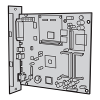
Main motor gear drive
Main motor cable
LVPS/HVPS
Engine board
Warning: Do not
replace the engine
board and controller
board at the same
time. Each board
contains the printer
settings. When either
of these boards is new,
it obtains the settings
from the other board.
Settings are lost when
both are new and
replaced at the same
time.
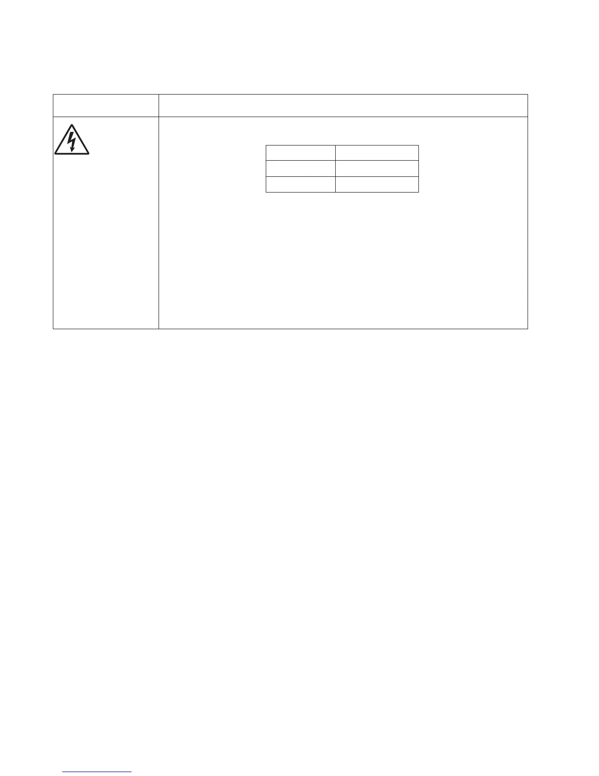
Turn off the printer, and unplug the main motor cable at J17 on the engine board. Turn on
the printer, and check for the following voltages at J17:
Verify ground at pin 5 for both the card and cable.
• If these voltages are correct, then check the main motor cable for continuity.
- Remove the left side cover to access the connector on the motor.
- If continuity exists on each wire, then replace the main motor gear drive which
includes the motor.
- If continuity does not exist on one or more of the wires, then call the next level of
support.
J17 pins Voltages
Pins 1-4, 6 Approx. 5 V dc
Pins 7-9 18 V dc-24 V dc
• If these voltages are not correct, then see “Controller and engine board connector
pin values” on page 2-6. Alternatively, replace the engine board. See “Engine board
removal” on page 2-15.