Back to Contents Page
Processor Module
Dell™Inspiron™9400ServiceManual
Removing the Processor Module
Replacing the Processor Module
Removing the Processor Module
1. Follow the instructions in Before Working Inside Your Computer.
2. Remove the hinge cover (see Removing the Hinge Cover).
3. Remove the keyboard (see Keyboard).
4. Remove the display assembly (see Removing the Display Assembly).
5. Remove the palm rest (see Removing the Palm Rest).
6. Remove the processor thermal-cooling assembly (see Removing the Processor Thermal-Cooling Assembly).
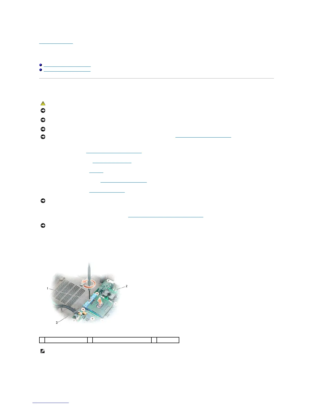
7. Loosen the ZIF socket to remove the processor module.
To loosen the ZIF socket, use a small, flat-blade screwdriver and rotate the ZIF-socket cam screw counterclockwise until it comes to the cam stop.
8. Lift the processor module from the ZIF socket.
CAUTION: Before you begin the following procedure, see the safety instructions in the Product Information Guide.
NOTICE: To avoid electrostatic discharge, ground yourself by using a wrist grounding strap or by periodically touching an unpainted metal surface (such
as the back panel) on the computer.
NOTICE: Do not touch the processor die. Press and hold the processor down on the substrate on which the die is mounted while turning the cam screw
to prevent intermittent contact between the cam screw and processor.
NOTICE: To avoid damage to the processor, hold the screwdriver so that it is perpendicular to the processor when turning the cam screw.
NOTICE: To help prevent damage to the system board, remove the main battery (see Before Working Inside Your Computer) before working inside the
computer.
NOTICE: To ensure maximum cooling for the processor, do not touch the heat transfer areas on the processor thermal-cooling assembly. The oils in
your skin reduce the heat transfer capability of the thermal pads.
NOTICE: When removing the processor module, pull the module straight up. Be careful not to bend the pins on the processor module.
pin-1 corner of microprocessor
NOTE: The ZIF-socket cam screw secures the processor to the system board. Take note of the arrow on the ZIF-socket cam screw, which indicates the
direction to turn the cam screw.
 Loading...