 Loading...
Do you have a question about the Dell Inspiron 9400 and is the answer not in the manual?
| Hard Drive Interface | SATA |
|---|---|
| Battery | 6-cell or 9-cell Lithium Ion |
| Processor | Intel Core Duo T2400 / T2500 |
| RAM | Up to 2GB DDR2 SDRAM |
| Display | 17-inch WXGA+ (1440x900) or WUXGA (1920x1200) |
| Graphics | NVIDIA GeForce Go 7800 |
| Optical Drive | DVD+/-RW |
| Operating System | Windows XP Media Center Edition or Windows XP Professional |
| Chipset | Intel 945PM Express |
| Wireless | Intel PRO/Wireless 3945ABG |
| Dimensions | 15.5 x 11.3 x 1.6 inches |
| Storage | 60GB / 80GB / 100GB / 120GB 5400RPM or 100GB 7200RPM |
Procedure to remove the battery latch assembly from the computer, involving several component removals.
Procedure to install a new battery latch assembly into the computer base.
Steps to remove the internal Bluetooth wireless card, including screw and cover removal.
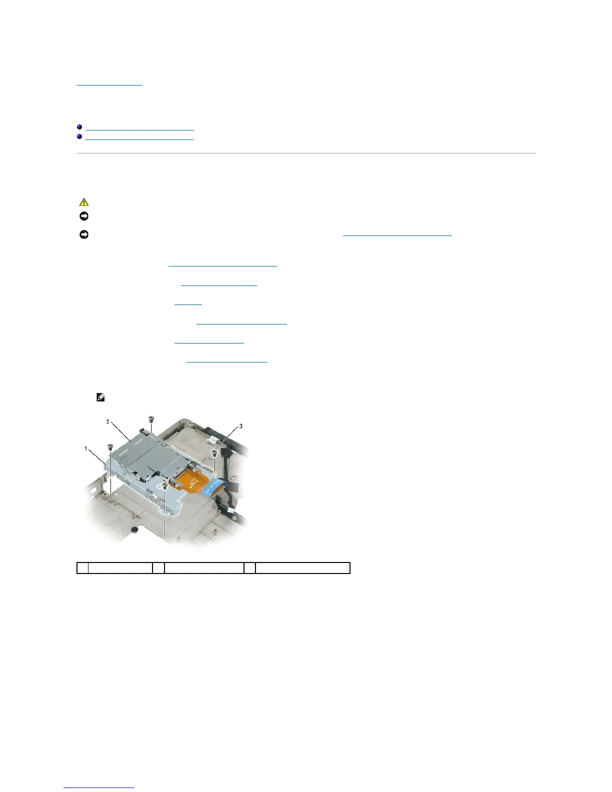
Procedure detailing the removal of the ExpressCard cage, involving disconnection and screw removal.
Steps to remove the Mini-Card, including cover, antenna cables, and securing clips.
Procedure for installing a new Mini-Card into its connector and securing it.
Instructions to disconnect and remove the coin-cell battery from its compartment.
Procedure for installing a new coin-cell battery and connecting its cable.
Detailed steps to remove the processor module using the ZIF socket.
Procedure for correctly seating and securing a new processor module into the ZIF socket.
Instructions to loosen captive screws and lift the processor thermal-cooling assembly.
Procedure for placing a new thermal pad and reattaching the thermal-cooling assembly.
Procedures for removing and replacing the entire display assembly.
Steps to carefully remove and replace the display bezel surrounding the screen.
Instructions for disconnecting cables and lifting the display panel from the back cover.
Procedure to remove and replace the display latch mechanism and its spring.
Steps to disconnect and remove the system fan(s) from the computer base.
Procedure to remove the hard drive, including screw removal and sliding it out.
Steps for installing a new hard drive, including OS and driver reinstallation.
Instructions for packaging and returning an old hard drive to Dell.
Procedure to carefully pry and remove the hinge cover.
Instructions to snap the hinge cover back into place.
Steps to disconnect and remove the keyboard, including screws and cable.
Procedure to release securing clips and remove memory modules.
Steps for aligning, sliding, and securing new memory modules into slots.
Procedure to remove the modem, involving screws, pull-tab, and cable disconnection.
Steps to connect the modem cable and secure the modem to the system board.
Steps to remove the optical drive using a security screw and indentation.
Procedure to remove the palm rest, involving multiple component removals and screws.
Steps to reconnect components and snap the palm rest back into place.
Details pin assignments for the USB connector.
Details pin assignments for the video connector (VGA).
Details pin assignments for the S-Video TV-Out connector.
Details pin assignments for the IEEE 1394 (FireWire) connector.
Procedure to disconnect speaker cables and remove the speakers.
Steps to secure speakers, connect cables, and re-route them.
Instructions to loosen screws and disconnect the subwoofer cable connector.
Detailed steps to remove the system board, involving numerous component disconnections.
Procedure for installing a new system board and updating BIOS with Service Tag.
Steps to disconnect the USB port board cable and remove it.
Procedure to insert the USB port board and secure it with a screw.
Instructions to loosen screws and lift the video card/thermal-cooling assembly.
Procedure to align and press down the video card/thermal-cooling assembly.