Dell
™
Latitude™ E6420 XFR Service Manual
Page 42
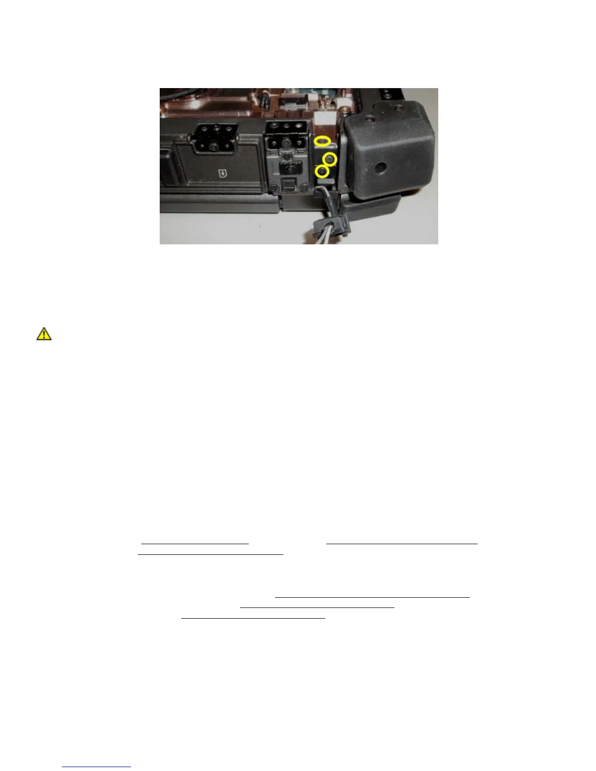
10. Remove the three M2.5 x 8-mm screws from each hinge.
11. Turn the computer topside up.
12. Open the display to 90 degrees and lift the display assembly off the base assembly.
22.2 Replacing the Display Assembly
CAUTION: Before you begin any of the procedures in this section, follow the safety
instructions that shipped with your computer.
1. Position the cables on the display assembly away from the base assembly.
2. Align the display hinges with the holes in the base of the computer, and lower the display into place.
3. Close the display and turn the computer upside down.
4. Replace the three M2.5 x 8-mm screws on each hinge. For each hinge, install the bottom side screw first,
then install the two rear screws.
5. Route the cables through each chassis cable channel.
6. Install the cable bundle gromments by pressing them into gromment channels.
7. Route the LVDS cable in the base assembly. The base assembly contains retention features along the cable
route to secure the LVDS cable.
8. Replace the mylar cable cover.
9. Reconnect the LVDS cable to the system board. Pre-bend the LVDS cable at the connector if this is a new
installation of the back cover.
10. Install the LVDS retention bracket.
11. Replace and tighten the two M2x3 mm screws securing the LVDS cable retention backet to the base assembly.
12. Route and reconnect all antenna cables to the appropriate cards(RF passthru, WLAN, WWAN, and WPAN).
13. Depending on the cards in your computer configuration, connect the antenna cables to their respective card:
For WWAN, see
Replacing a WWAN Card. For WPAN, see Replacing a WPAN (UWB/BT) Card.
For WLAN, see
Replacing the WLAN/WiMax Card. For RF Passthru, see Replacing the RF Passthru board.
Place any unused antenna cables in the base assembly cable holders next to the card slot.
14. If the system has the optional Touch Controller USB cable in the Display assembly, reconnect the cable to the
I/O board.
15. Replace the display cable channel covers (see
Replacing the Display Cable Channel Covers).
16. Replace the bottom access panel (see
Replacing the Bottom Access Panel).
17. Follow the procedures in
After Working on Your Computer.
 Loading...