Dell
™
Latitude™ E6420 XFR Service Manual
Page 58
The system board’s BIOS chip contains the Service Tag, which is also visible on a barcode label on the bottom of the
computer. The replacement kit for the system board includes media that provides a utility for transferring the Service
Tag to the replacement system board.
NOTE: The replacement kit for the system board also includes media that provides a utility to set the
system board as XFR, and a tech sheet for running this utility.
31.1 Removing the System Board Assembly
CAUTION: Before you begin any of the procedures in this section, follow the safety
instructions that shipped with your computer.
1. Follow the instructions in
Before Working on Your Computer.
2. Remove palm rest(see
Removing the Palm rest).
3. Remove the VGA panel cover (see
Removing the VGA Panel Cover).
4. Remove the coin-cell battery (see
Removing the Coin Cell Battery).
5. Remove any mini-pci cards from the WWAN/FCM card slot, WLAN/WiMax card slot, and from the
WPAN/UWB/FCM card slot, if present (see Chapter 5, 6, 7 and 8 for removal procedures).
6. Remove the memory modules (see
Removing a Memory Module).
Remove the fan, processor heatsink assembly and processor (see
Removing the Processor Module).
7. Remove the hard drive (see
Removing the Hard Drive).
8. Remove the modular drive (see
Removing the Modular Drive).
9. Remove the express card assembly (see
Removing the Express Card Assembly).
10. Disconnect the Audio Cable and USB Cable from the connections on the right side of the chassis and pull the
cables from the routing channels so they do not interfere with the system board removal.
11. Disconnect the media board ribbon cable from the system board.
12. Disconnect the smartcard ribbon cable from the system board.
13. Disconnect the Bluetooth Module cable from the system board.
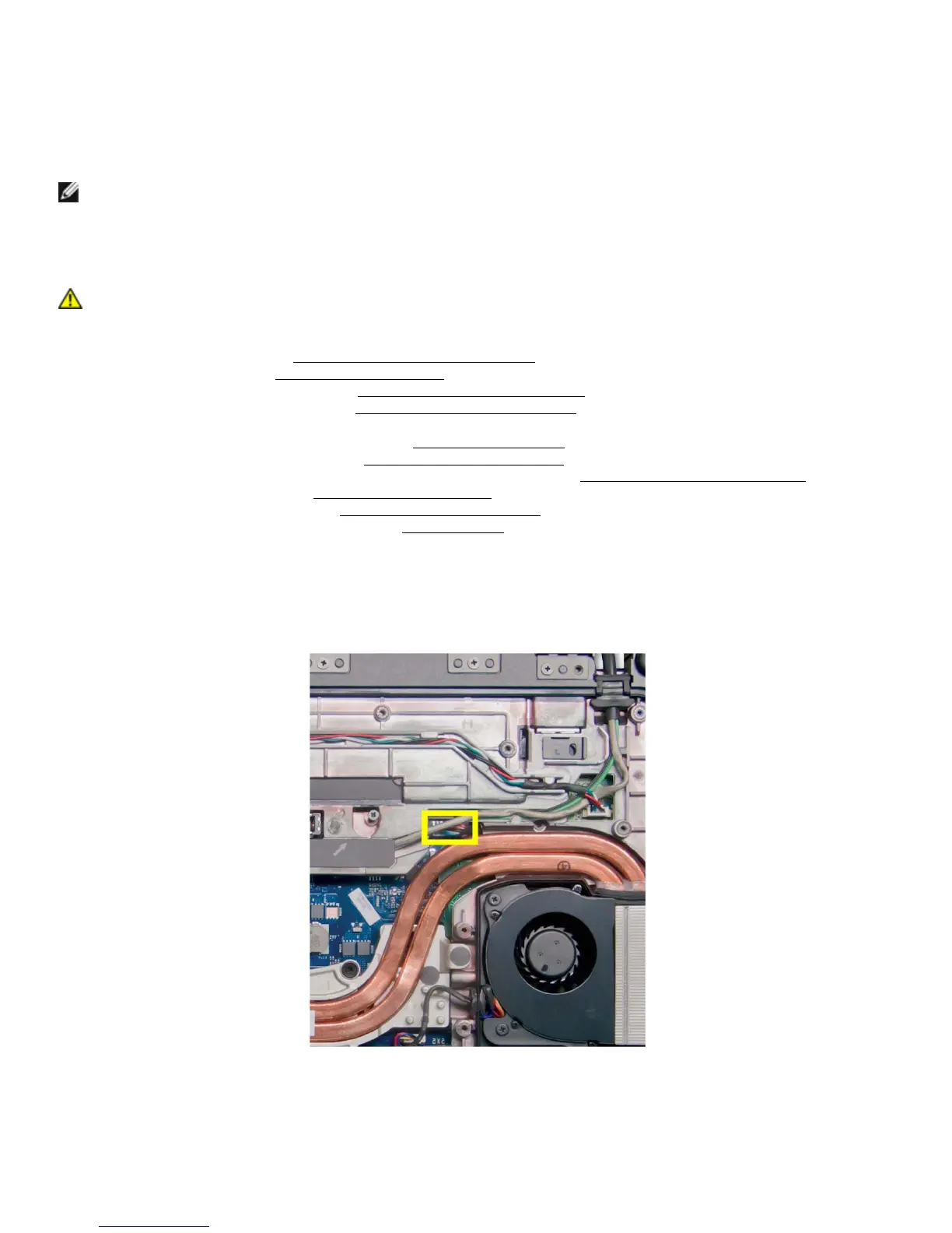
14. Disconnect the DC power cable from the system board.
15. Remove the one M2.5 x 10-mm screw that secures the right rear of the system board to the chassis.
 Loading...