


Do you have a question about the Dell Latitude E6400 XFR and is the answer not in the manual?
| Processor | Intel Core 2 Duo |
|---|---|
| Storage | Up to 250GB HDD or 128GB SSD |
| Warranty | 3-year limited warranty |
| Display | 14.1-inch WXGA (1280x800) |
| RAM | Up to 8GB DDR2 |
| Graphics | Intel GMA 4500MHD |
| Operating System | Windows Vista, Windows XP |
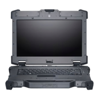
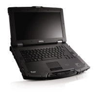
| Rugged Features | MIL-STD-810F |
| Chipset | Intel GM45 Express Chipset |
| Wireless | Wi-Fi 802.11a/g/n, Bluetooth 2.1 |
| Connectivity | Gigabit Ethernet, Modem |
| Ports | VGA |
| Card Slots | Smart Card Reader |
| Battery | 6-cell or 9-cell Lithium Ion |
| Networking | Gigabit Ethernet |
| Security | Trusted Platform Module (TPM), Fingerprint Reader, Smart Card Reader |