 Loading...


Do you have a question about the Dell OPTIPLEX 740 and is the answer not in the manual?
| Audio | Integrated High Definition Audio |
|---|---|
| Processor | AMD Athlon 64 X2, AMD Sempron |
| Memory | Up to 8GB DDR2 |
| Storage | SATA HDD |
| Graphics | Optional discrete graphics |
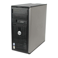
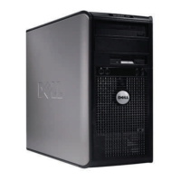
| Form Factor | Mini Tower |
| Expansion Slots | 1 PCI-e x16 |
| Optical Drive | DVD-ROM, DVD+/-RW |
| Network | Integrated 10/100/1000 Ethernet |
| Power Supply | Mini-Tower: 305W |
| Ports | USB 2.0, serial, parallel, VGA, audio |
| Operating System | Windows XP |