Display: Dell XPS M1710 Service Manual
file:///C|/Users/santhosh_v.ASIA-PACIFIC/Desktop/Hawke/New%20folder/display.htm[2/21/2014 11:23:47 AM]
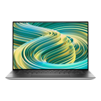
2. Align the display assembly over the screw holes in the base of the computer.
NOTE: The left hinge assembly has a small tab that you must first insert underneath the edge of the palm rest.
1 tab
NOTE: When you replace the four screws, ensure that you tighten them in the order indicated by the labels "1," "2,"
"3," and "4" on the display hinges.
3. Replace the four M2.5 x 5-mm screws.
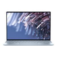
4. Connect the display cable to the system board.
5. Reroute the display cable into the cable channel.
6. Connect the LED cable to the system board.
7. Reroute the LED cable in the cable channel.
8. Replace the hinge cover (see Replacing the Hinge Cover
).
9. If a Mini-Card is installed, connect the antenna cables to the card (see Mini-Card
). If one is not installed, tuck the
antenna cables into their secured location.
10. Replace the Mini-Card cover.

 Loading...