Chapter 6 Control Modes of Operation|ASDA-A&A+ Series
Revision April 2009 6-35
6.5 Control Modes Selection
Except signal control mode operation, ASDA-A and ASDA-A+ series servo drives also provide Pt-S, Pr-S, S-
T, Pt-T, Pr-T these five multiple modes for the users to select.
1) Speed / Position mode selection: Pt-S, Pr-S
2) Speed / Torque mode selection: S-T
3) Torque / Position mode selection: Pt-T, Pr-T
Mode Name Code Description
Pt-S 06 Either Pt or S control mode can be selected via the Digital Inputs (DI)
Pt-T 07 Either Pt or T control mode can be selected via the Digital Inputs (DI)
Pr-S 08 Either Pr or S control mode can be selected via the Digital Inputs (DI)
Pr-T 09 Either Pr or T control mode can be selected via the Digital Inputs (DI)
Dual Mode
S-T 10 Either S or T control mode can be selected via the Digital Inputs (DI)
Sz and Tz mode selection is not provided. In order to avoid using too much DI inputs, we recommend that
the users can use external analog signal as input command in speed and torque mode to reduce the use of
DI inputs (SPD0~1 or TCM0~1). In position mode, we recommend that the users can use Pt mode to input
pulse to reduce the use of DI inputs (POS0~2).
Please refer to table 3.B and table 3.C in section 3.3.2 to see the default pin number of DI/DO signal.
6.5.1 Speed / Position Control Mode Selection
Pt-S Mode / Pr-S Mode:
The command source of Pt-S mode is from external input pulse. The command source of Pr-S mode is
from internal parameters (P1-15 to P1-30). The speed command can be the external analog voltage or
internal parameters (P1-09 to P1-11). The speed and position mode switching is controlled by the S-P
signal. The selection will be more complicated when the position of Pr-S mode and speed command are
both selected through DI signal.
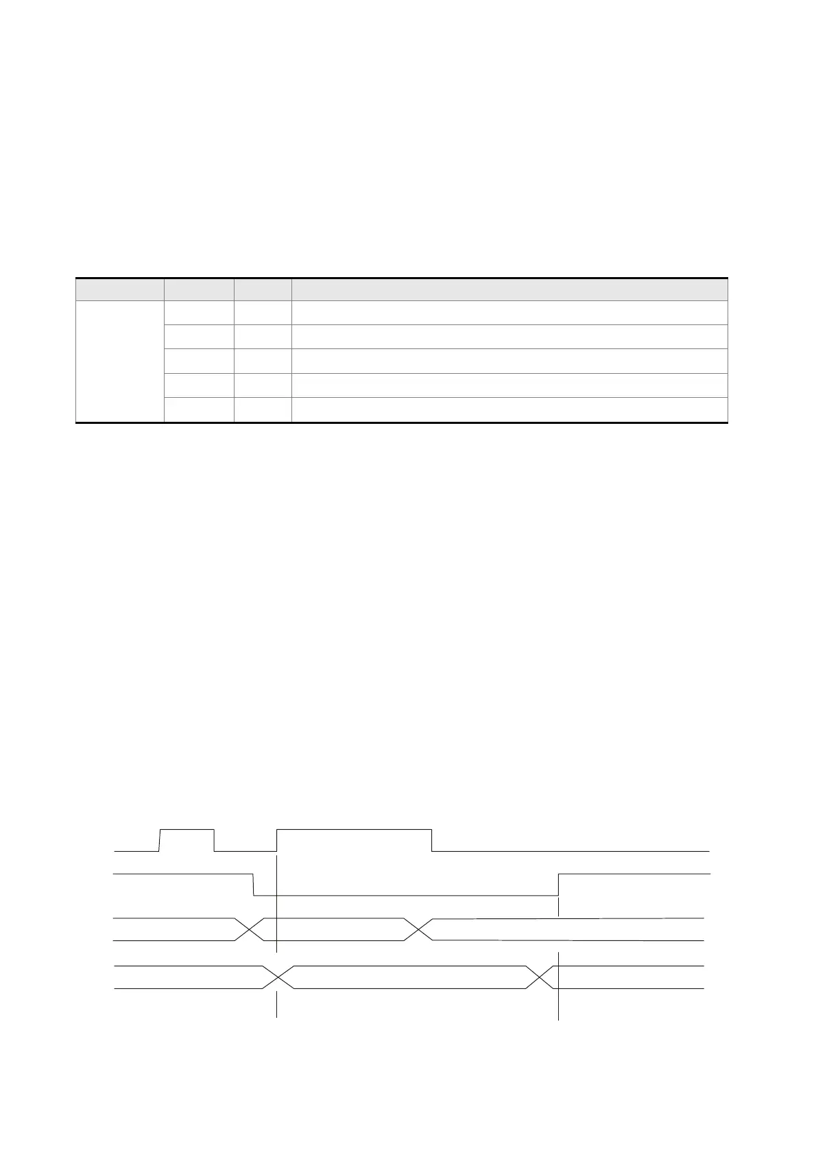
The timing chart of speed / position control mode selection is shown as the figure below:
TR
S-P
POS0-2 NOT CARE
POS0-2 NOT CARE
POS0-2 VALID
SPD0-1 VALID
SPD0~1 NOT CARE SPD0-1 VALID
Speed control mode
Position control mode
Speed control mode
Fi
ure 1. : Speed / Position Control Mode Selectio
Call 1(800)985-6929 for Sales
Call 1(800)985-6929 for Sales
 Loading...