EasyManuals Logo
Home>Delta Electronics>Servo Drives>ASDA-A Series

Delta Electronics ASDA-A Series User Manual

Delta Electronics ASDA-A Series
383 pages
To Next Page IconTo Next Page
To Previous Page IconTo Previous Page
Page #50 background imageLoading...
Page #50 background image
Chapter 3 Connections and Wiring|ASDA-A&A+ Series
Revision April 2009 3-17
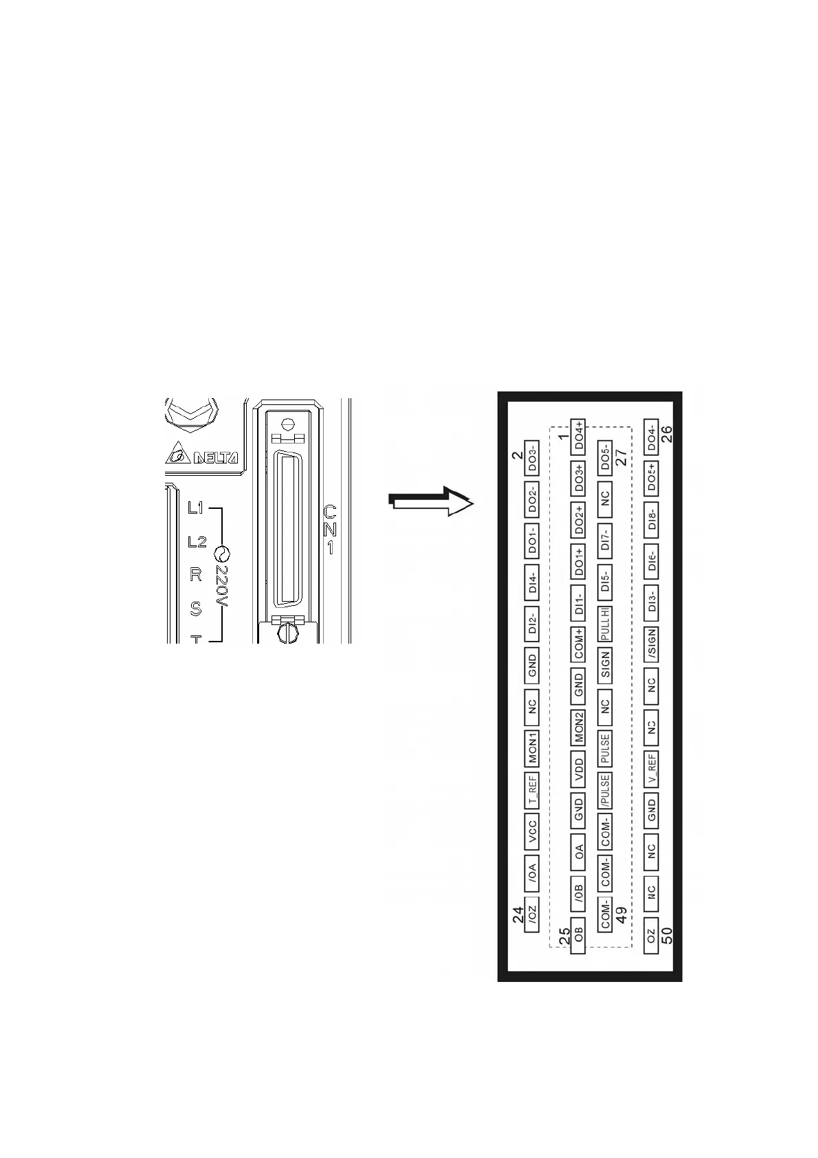
3.3 Input / Output Interface Connector -CN1
The CN1 Interface Connector provides access to three signal groups:
i General interface for the analog speed and torque control, encoder reference signal from the motor,
pulse / direction inputs, and reference voltages.
ii 8 programmable Digital Inputs (DI), can be set via parameters P2-10 ~ P2-17
iii 5 programmable Digital Outputs (DO), can be set via parameters P2-18 ~ P2-22
A detailed explanation of each group is available in Section 3.3.2, Tables 3.A, 3.B & 3.C.
3.3.1 CN1 Terminal Identification
Figure 3.8 The Layout of CN1 Drive Connector
Call 1(800)985-6929 for Sales
deltaacdrives.com
sales@deltaacdrives.com
Call 1(800)985-6929 for Sales
deltaacdrives.com
sales@deltaacdrives.com

Table of Contents

Other manuals for Delta Electronics ASDA-A Series

Questions and Answers:

Question and Answer IconNeed help?

Do you have a question about the Delta Electronics ASDA-A Series and is the answer not in the manual?

Delta Electronics ASDA-A Series Specifications

General IconGeneral
BrandDelta Electronics
ModelASDA-A Series
CategoryServo Drives
LanguageEnglish

Related product manuals