Chapter 5 Understanding Common Devices
5-9
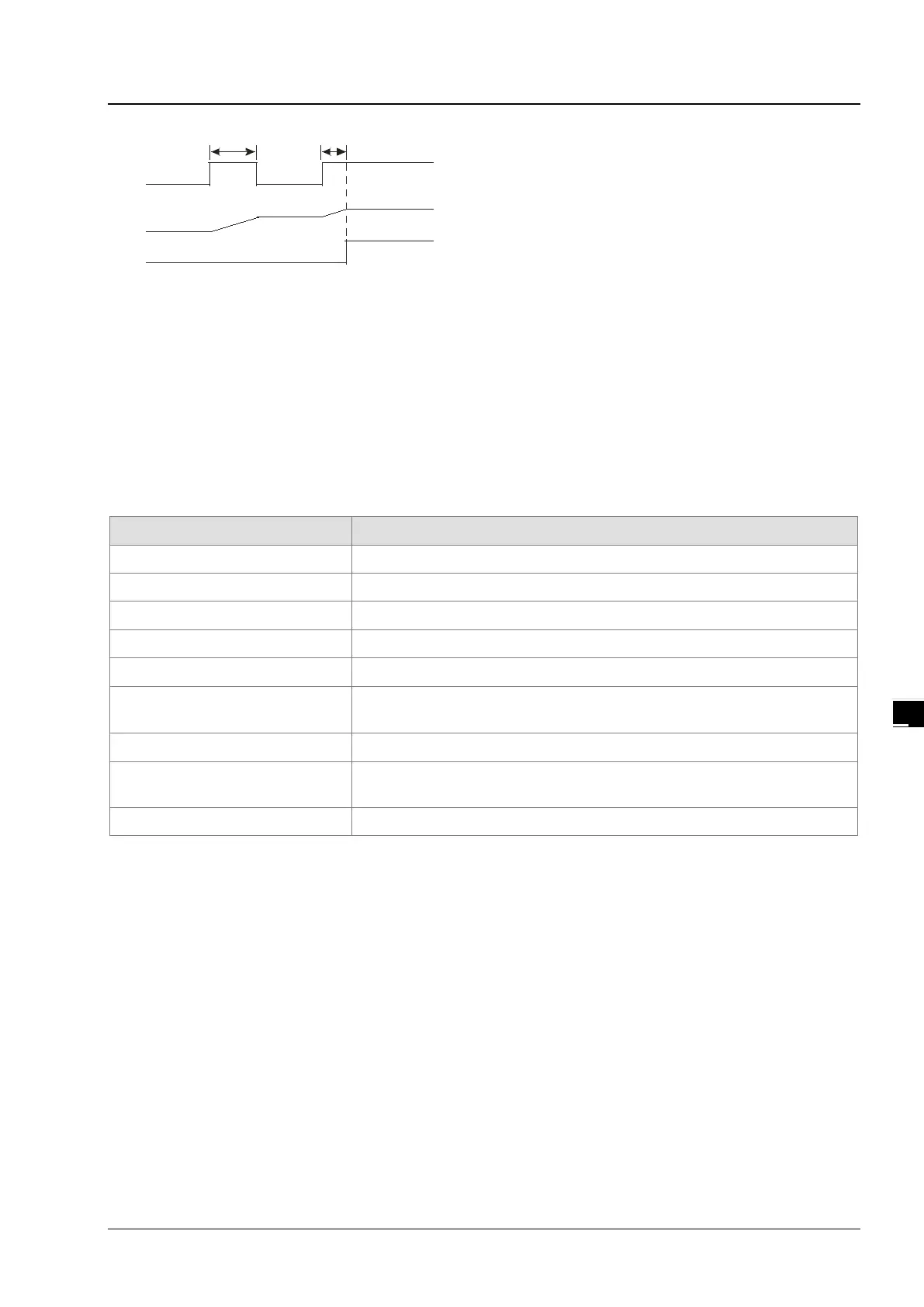
X0.0
T2
Y0.0
SV: K100
T1+T2=10sec
T250(PV)
T1
Timer used in the function block
T1920~T2047 are the timers which users can use in the functional block or the interrupt.
When the instruction TMR or END is executed, the timer used in the functional block begins to count. As the value of
the timer matches the setting value, the output coil is ON.
If the general-purpose timer is used in the functional block or the interrupt, and the functional is not executed, the timer
can not count correctly.
5.2.13. Counters (C)
Specifications of the 16-bit counter
Type General type
Number C0~C2047
Specification of the setting value
The setting value can be either the constant or the value in the data register.
Change of the current value
The counter stops counting when the value of the counter matches the setting
value.
Output contact The contact is ON when the value of the counter matches the setting value.
Reset
When the instruction RST is executed, the current value is cleared to zero, and
the contact is reset of OFF.
Action of the contact After the scan is complete, the contact acts.
The function of the counter:
Each time the input switches from OFF to ON, the value of the counter increases by one increment. When the value of the
counter matches the setting value, the output coil is ON. You can use either the decimal constant or the value in the data
register as the setting value.
The 16-bit counter:
1. Setting range: 0~32,767 (The setting values 0 and 1 mean the same thing in that the output contact is ON when the
counter counts for the first time.)
2. For the general-purpose counter, the current value of the counter is cleared when there is a power cut. If the counter is
the latched one, the current value of the counter and the state of the contact before the power cut will be retained. The
latched counter counts from the current value when the power supply is restored.
3. If you use the instruction MOV or ISPSoft to transmit a value bigger than the setting value to the current value register
C0, the contact of the counter C0 will be ON and the current value will become the same as the setting value next time
X0.1 is switched from OFF to ON.