AS Series Operation Manual
2-73
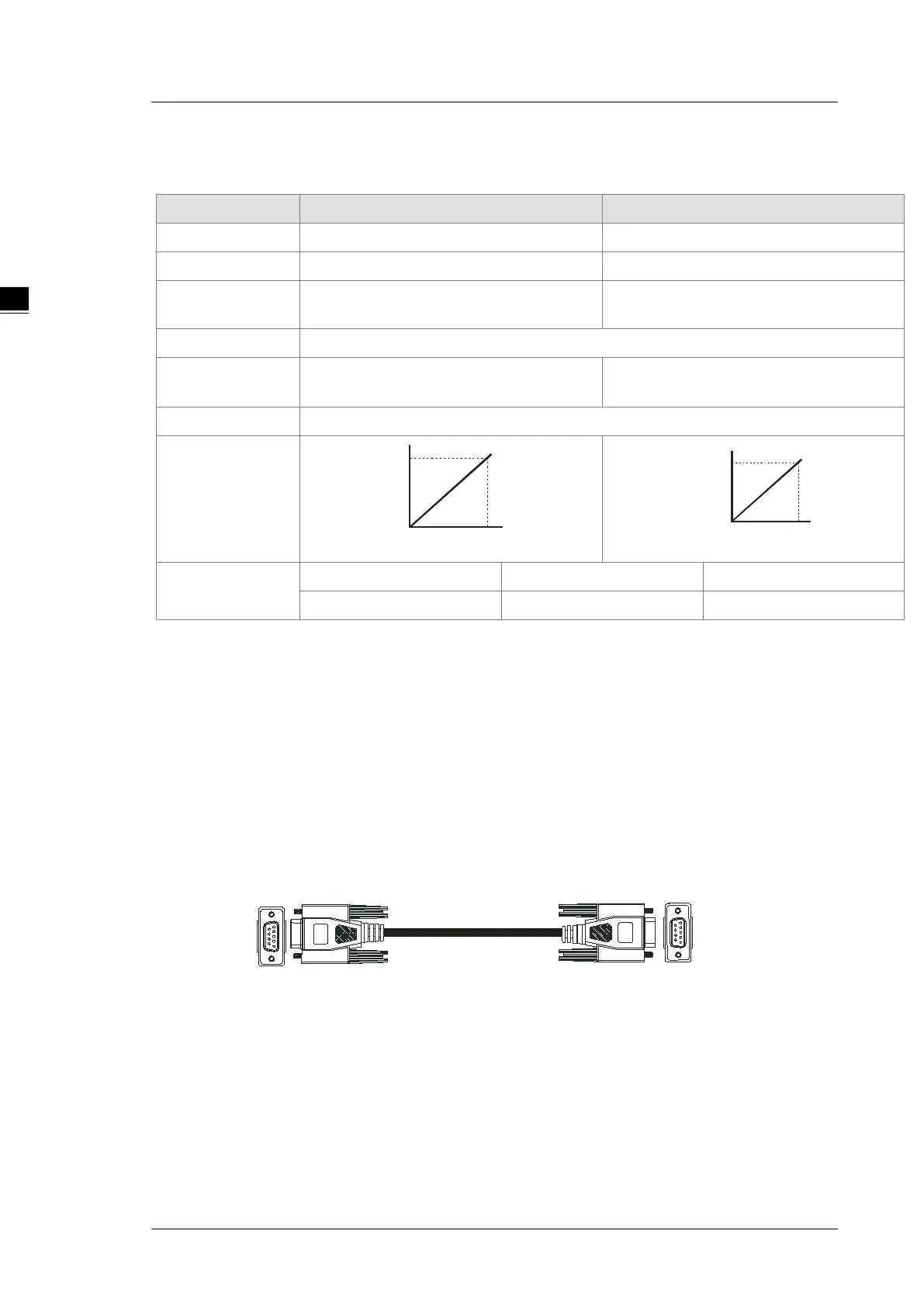
AS-F2DA
Two DC analog signal output channels:
Item Voltage Output Current Output
Analog Signal
0 V - 10 V 4 mA - 20 mA
Resolution
12-bit
12-bit
Digital Conversion
Limit
0 - 4000 0 - 4000
Error Rate
room temperature: ±0.5% ; full temperature range: ±1.0%
Impedance
Allowance
≥1 kΩ ≤500 Ω
Conversion Time*
1
2ms / CH
Characteristic
Curve
Digital Value Input
Voltage Output
10V
4000
0
Digital Value Input
Current Output
20mA
4000
4
Digital Value
Output*
2
Card 1 SR172 (CH1) SR173 (CH2)
Card 2 SR174 (CH1) SR175 (CH2)
*1: The conversion time is the time for each channel to convert signals to hardware input signals. If you need
to calculate a complete conversion time, you need to add the PLC scan time.
*2: Use the MOV instruction to move the value to the SR to obtain the corresponding voltage output value.
AS-F232
The AS series PLC is built with COM1 (RS-485), and COM2 (RS-485). You can use this extension card for
communication with different interfaces such as RS-232 and a PC. The Communication functions are the
same as the built-in ones. You can set the communication port as a slave or a master node. After installing the
extension card, go to the HWCONFIG in the ISPSoft for communication setup.
Wiring example
DB9 male to DB9 female (standard cable)
AS-F232
(DB9 female)
+ +
Superior
machine
 Loading...