Chapter 12 Troubleshooting
12-7
12.2
Troubleshooting for CPU Modules
Check the LED indicators and the error codes from the CPU module and refer to the following table for troubleshooting.
V in the Log column indicates the error is recorded in the log. X in the Log column indicates the error is not recorded in
the log. H in the Log column indicates whether or not you can set recording the error in the log in HWCONFIG.
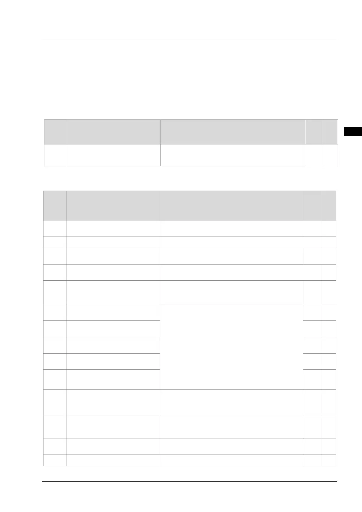
12.2.1
ERROR LED Indicators Are ON
Error
Code
Description Solution Flag Log
000A Scan timeout
1. Check the setting of the watchdog timer in HWCONFIG.
2. Check whether the program causes a long scan time
SM8 V
12.2.2
ERROR LED Indicators Blinking Every 0.5 Seconds
Error
Code
(16#)
Description Solution Flag Log
000C
The program in the PLC is
damaged.
Download the program again. SM9 V
0010 CPU memory is denied. Contact the factory. SM9 V
002E
CPU external memory access is
Contact the factory. SM9 V
002F
PLC programs are not consistent
with the system logs.
Download the program again. SM34 V
0070
The arrangement of the function
cards is not consistent with the
settings.
Check whether the settings in HWCONFIG are
consistent with the arrangement of the function cards.
SM10 V
0102
The interrupt number exceeds the
Check the syntax error step in the program. Modify and
compile the program and then download the program
again.
SM5 X
0202
The MC instruction exceeds the
SM5 X
0302
The MCR instruction exceeds the
SM5 X
0D03
The operands used in DHSCS are
SM5 X
0E05
The operands HCXXX used in
DCNT are not used properly.
SM5 X
1300
-
Errors occurred in the remote
modules
Refer to Section 12.3.4 for more information on the error
codes for the remote modules.
SM30 V
1402
The arrangement of the I/O
modules is not consistent with the
Check whether the settings in HWCONFIG are
consistent with the arrangement of the I/O modules.
SM10 V
140B
More than four communication
Check the total number of communication modules
SM10 V
140D More than 32 extension modules.
Check the total number of extension modules (maximum
SM10 V
 Loading...