Appendix A. Modbus ProtocolC2000 Plus
A-9
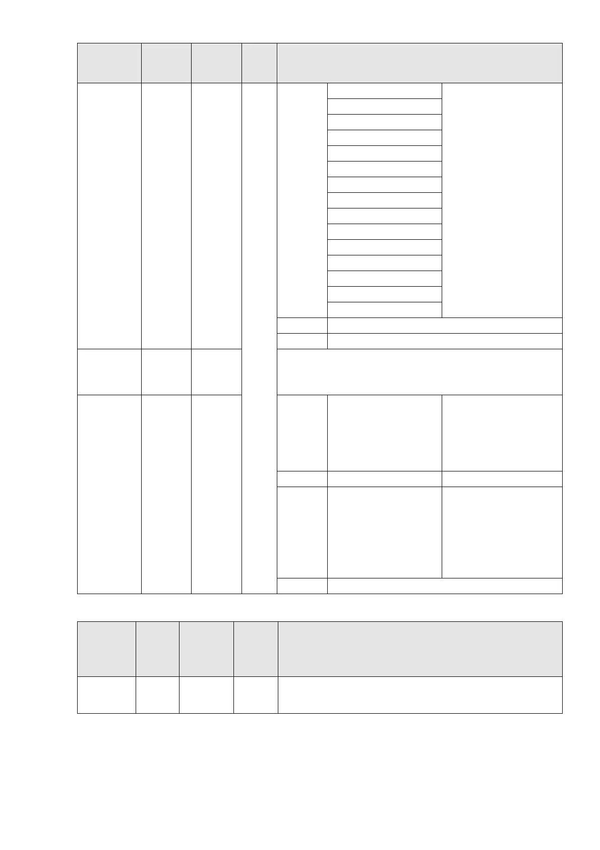
Function
Name
Modbus
Address
Attribute
(Function
Code)
Size Description
0001B: 1st step speed
0010B: 2nd step speed
0011B: 3rd step speed
0100B: 4th step speed
0101B: 5th step speed
0110B: 6th step speed
0111B: 7th step speed
1000B: 8th step speed
1001B: 9th step speed
1010B: 10th step speed
1011B: 11th step speed
1100B: 12th step speed
1101B: 13th step speed
1110B: 14th step speed
1111B: 15th step speed
bit12 1: Enable bit06–11 function
bit15 Reserved
Frequency
command
2001H
R (03H) /
W (06H,
10H)
Frequency command (XXX.XX Hz). There are two decimal
places for general-purpose drives.
Fault / control
command
source
2002H
R (03H) /
W (06H,
10H)
bit0
1: External Fault (E.F.)
ON
To trigger an external fault
to the drive to make it
stop running. Drive’s stop
method can be set
through drive parameters.
bit1 1: Reset To clear the fault status
bit2 1: Base block (B.B) ON
To trigger an external
base block to the drive to
suspend the operation.
When bit = 0 and clear BB
situation, the drive returns
to the previous operation.
bit15~3 Reserved
5. Status monitor read only (21xx): communication station address is Pr.09-00 setting value
Function
Name
Modbus
Address
Attribute
(Function
Code)
Size Description
Fault status 2100H R(03H) U16
bit7~0: Fault code
bit15~8: Warning code
 Loading...