Chapter 12 Descriptions of Parameter SettingsC2000 Plus
12.1-10-5
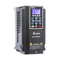
2. Semi-closed loop control method: Type B (Encoder is installed at the load side)
Since the encoder is installed at the load side, the drive can only realize the actual load position
movement, not the motor position movement. In this case, you must set the mechanical gear ratio
to convert the load position movement to motor position movement
A mechanical gear ratio error may occur if you use this control method. It is not recommended to
use this method because it has a poorer performance in motor driving.
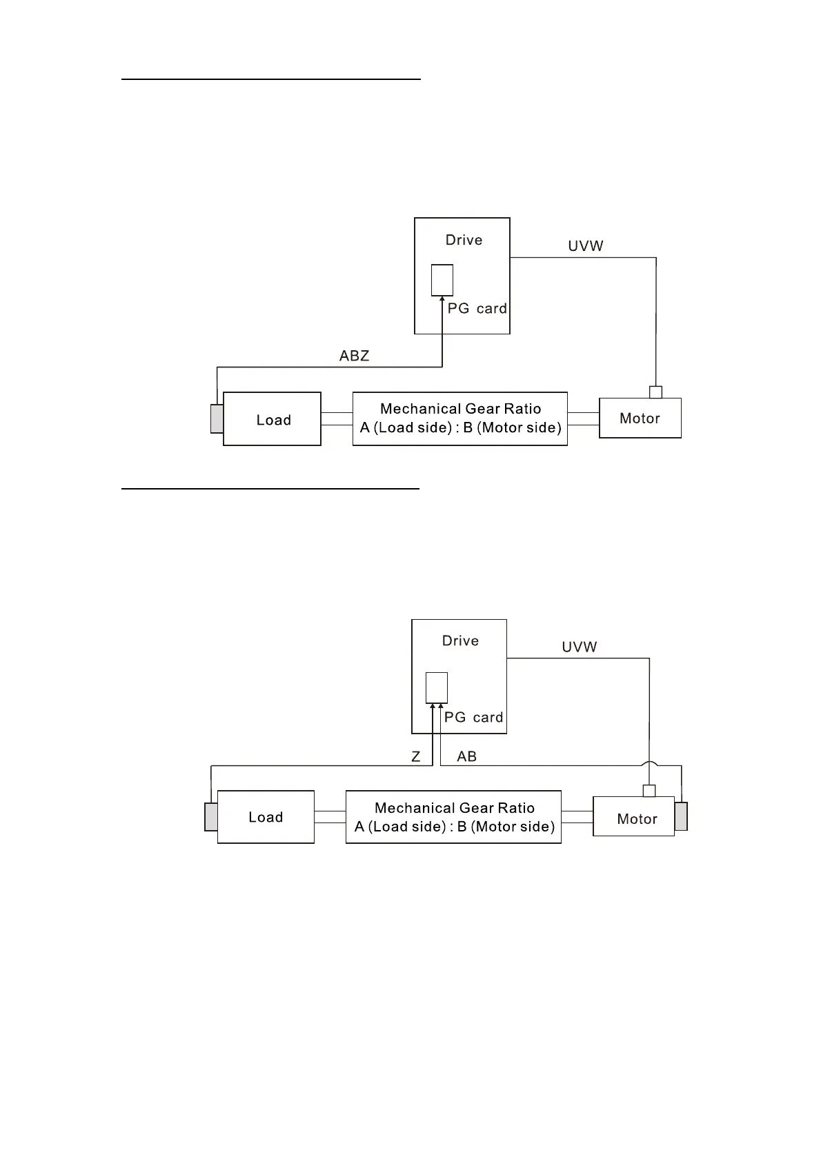
3. Fully-closed loop control method: Type A (Encoder is installed at the motor side, and Z-phase
signal comes from the load side)
The encoder is installed at the motor side, and the Z-phase signal comes from the load side, so
the drive can realize both the motor position movement and actual load position movement.
However, because there is only Z-phase signal for the actual position movement, set Pr.11-62 /
Pr.11-63 (PPR Number at Load Side High / Low Byte).
Example 1:
When the encoder is installed at the load side, Pr.10-04 = 204 (Mechanical Gear A1 at Load Side),
and Pr.10-05 = 34 (Mechanical Gear B1 at Motor Side), then the mechanical gear ratio is A1:B1 =
204:34 = 6:1. In this case, set the frequency command = 2 Hz, then motor’s actual frequency is
12 Hz, and the frequency at the load side is 2 Hz.
Example 2:
Set the encoder PPR = 1024, Pr.10-04 = 20, and Pr.10-05 = 40. The motor’s one revolution is
equal to the load’s two revolutions after setting the mechanical gear ratio (frequency at the motor
side = 20 Hz; frequency at the load side = 400 Hz).
 Loading...