Chapter 12 Descriptions of Parameter SettingsC2000 Plus
12.1-10-4
10-04
Mechanical Gear at Load Side A1
10-05
Mechanical Gear at Motor Side B1
10-06
Mechanical Gear at Load Side A2
10-07
Mechanical Gear at Motor Side B2
Default: 100
Settings 1–65535
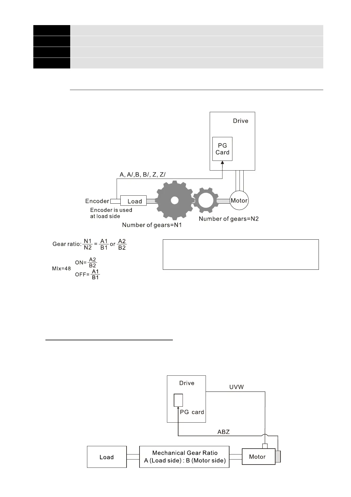
Use Pr.10-04–Pr.10-07 with the multi-function input terminal setting 48 to switch to Pr.10-04–
Pr.10-05 or Pr.10-06–Pr.10-07, as shown in the diagram below.
A1 = Mechanical Gear A1 at Load Side (Pr.10-04)
B1 = Mechanical Gear B1 at Motor Side (Pr.10-05)
A2 = Mechanical Gear A2 at Load Side (Pr.10-06)
B2 = Mechanical Gear B2 at Motor Side (Pr.10-07)
When using the single-point positioning function, consider the mechanical gear ratio and encoder
installation positions (use semi-closed loop control method when the encoder is installed at the
motor side or load side; use fully-closed loop control method when the encoder is installed at the
motor side and the Z-phase signal comes from the load side)
1. Semi-closed loop control method: Type A (Encoder is installed at the motor side)
Since the encoder is installed at the motor side, the drive can only realize the motor placement,
not the actual load placement. In this case, motor placement is regarded as load placement. Thus,
the mechanical gear ratio is 1:1
 Loading...