Chapter 12 Descriptions of Parameter SettingsC2000 Plus
12.1-13-2
Group setting 03: Fan
The following table lists the relevant fan setting application parameters.
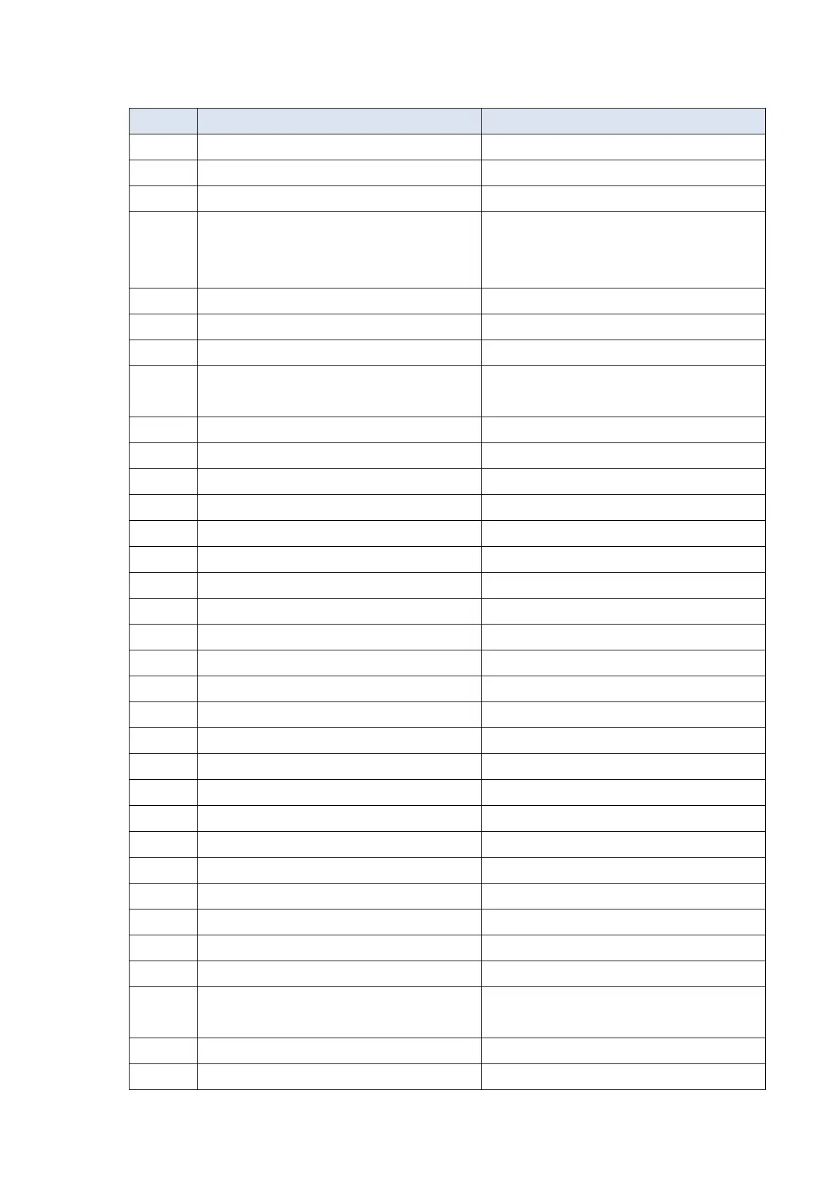
Pr. Explanation Settings
00-11 Speed Control Mode 0 (V/F control)
00-16 Duty Selection 0 (Normal load)
00-17 Carrier Frequency Default setting
00-20
Master Frequency Command Source
(AUTO) / Source Selection of The PID
Target
2 (External analog input)
00-21 Operation Command Source (AUTO) 1 (External terminals)
00-22 Stop Method 1 (Coast to stop)
00-23 Control of Motor Direction 1 (Disable reverse)
00-30
Master Frequency Command (HAND)
Source
0 (Digital keypad)
00-31 Operation Command (HAND) Source 0 (Digital keypad)
01-00 Maximum Operation Frequency Default setting
01-01 Motor 1 Rated / Base Frequency Default setting
01-02 Motor 1 Rated / Base Output Voltage Default setting
01-03 Motor 1 Mid-Point Frequency 1 Default setting
01-04 Motor 1 Mid-Point Voltage 1 Default setting
01-05 Motor 1 Mid-Point Frequency 2 Default setting
01-06 Motor 1 Mid-Point Voltage 2 Default setting
01-07 Motor 1 Minimum Output Frequency Default setting
01-08 Motor 1 Minimum Output Voltage Default setting
01-10 Output Frequency Upper Limit 50 (Hz)
01-11 Output Frequency Lower Limit 35 (Hz)
01-12 Acceleration Time 1 15 (s)
01-13 Deceleration Time 1 15 (s)
01-43 V/F Curve Selection 2 (Second V/F curve)
02-05 Multi-Function Input Command 5 (MI5) 16 (Rotating speed command from ACI)
03-00 Analog Input Selection (AVI)
1 (Frequency command)
03-01 Analog Input Selection (ACI) 1 (Frequency command)
03-28 AVI Terminal Input Selection 0 (0–10 V)
03-29 ACI Terminal Input Selection 1 (0–10 V)
03-31 AFM Output Selection 0 (0–10 V)
03-50 Analog Input Curve Selection 1 (three-point curve of AVI)
07-06 Restart After Momentary Power Loss
2 (Speed tracking by minimum output
frequency)
07-11 Number of Times of Restart after Fault 5 (times)
07-33 Auto-Restart Interval of Fault 60 (s)
 Loading...


