Chapter 12 Descriptions of Parameter SettingsC2000 Plus
12.1-14-2
When Pr.14-18 or Pr.14-19 = 0, the voltage input is 0–10 V; when Pr.14-18 or Pr.14-19 = 1, the
voltage input is 4–20 mA, and Pr.14-10 and Pr.14-11 are invalid.
When the setting is 1 or 2, the keypad displays the warning code “ANL”. It keeps blinking until
the ACI signal is recovered.
When the drive stops, the condition that causes the warning does not exist, so the warning
automatically disappears.
The ACI (4–20 mA) signal loss level is 3.6 mA, and the return level is 4 mA.
14-12
Extension Card Output Terminal Selection (AO10)
14-13
Extension Card Output Terminal Selection (AO11)
Default: 0
Settings 0–23
Refer to the function chart below for details setting.
Function Chart
Settings Functions Descriptions
0
Output frequency (Hz) Maximum frequency Pr.01-00 is processed as 100%.
1 Frequency command (Hz) Maximum frequency Pr.01-00 is processed as 100%.
2 Motor speed (Hz) Maximum frequency Pr.01-00 is processed as 100%.
3 Output current (rms) (2.5 × drive rated current) is processed as 100%
4 Output voltage (2 × motor rated voltage) is processed as 100%
5 DC bus voltage 450V (900V)=100%
6 Power factor -1.000–1.000=100%
7 Power (2 × drive rated power) is processed as 100%
8 Torque Full load torque = 100%
9 AVI 0–10 V = 0–100%
10 ACI 4–20 mA = 0–100%
11 AUI -10–10V = 0–100%
12 Iq current command (2.5 × drive rated current) is processed as 100%
13 Iq feedback value (2.5 × drive rated current) is processed as 100%
14 Id current command (2.5 × drive rated current) is processed as 100%
15 Id feedback value (2.5 × drive rated current) is processed as 100%
18 Torque command Motor rated torque of motor = 100%
19 PG2 frequency command Maximum frequency Pr.01-00 is processed as 100%.
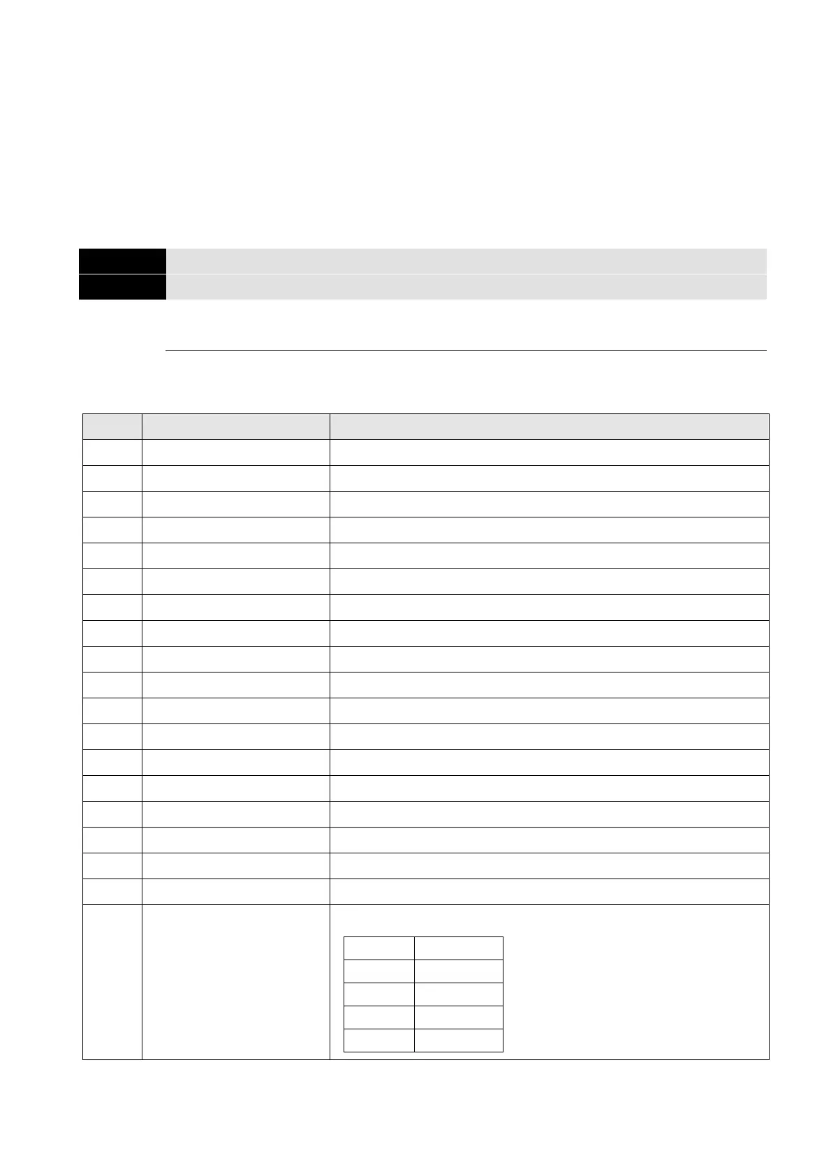
20 CANopen analog output
For CANopen communication analog output
Terminal Address
AFM1 2026-A1
AFM2 2026-A2
AO10 2026-AB
AO11 2026-AC
 Loading...