Chapter 12 Descriptions of Parameter SettingsC2000 Plus
12.1-14-3
Settings Functions Descriptions
21 RS-485 analog output
For RS-485 (InnerCOM / Modbus) control analog output
Terminal Address
AFM1 26A0H
AFM2 26A1H
AO10 26AAH
AO11 26ABH
22
Communication card
analog output
For communication analog output (CMC-EIP01, CMC-PN01,
CMC-DN01)
Terminal Address
AFM1 26A0H
AFM2 26A1H
AO10 26AAH
AO11 26ABH
23 Constant voltage output
Pr.03-32 controls the voltage output level.
0–100% of Pr.03-32 corresponds to 0–10 V of AFM.
25
CANopen and RS-485
analog output
For CANopen and InnerCOM control output
14-14
Analog Output 1 Gain (AO10)
14-15
Analog Output 1 Gain (AO11)
Default: 100.0
Settings 0.0–500.0%
Adjust the voltage level outputted to the analog meter from the analog signal (Pr.14-12,
Pr.14-13) output terminal AFM of the drive.
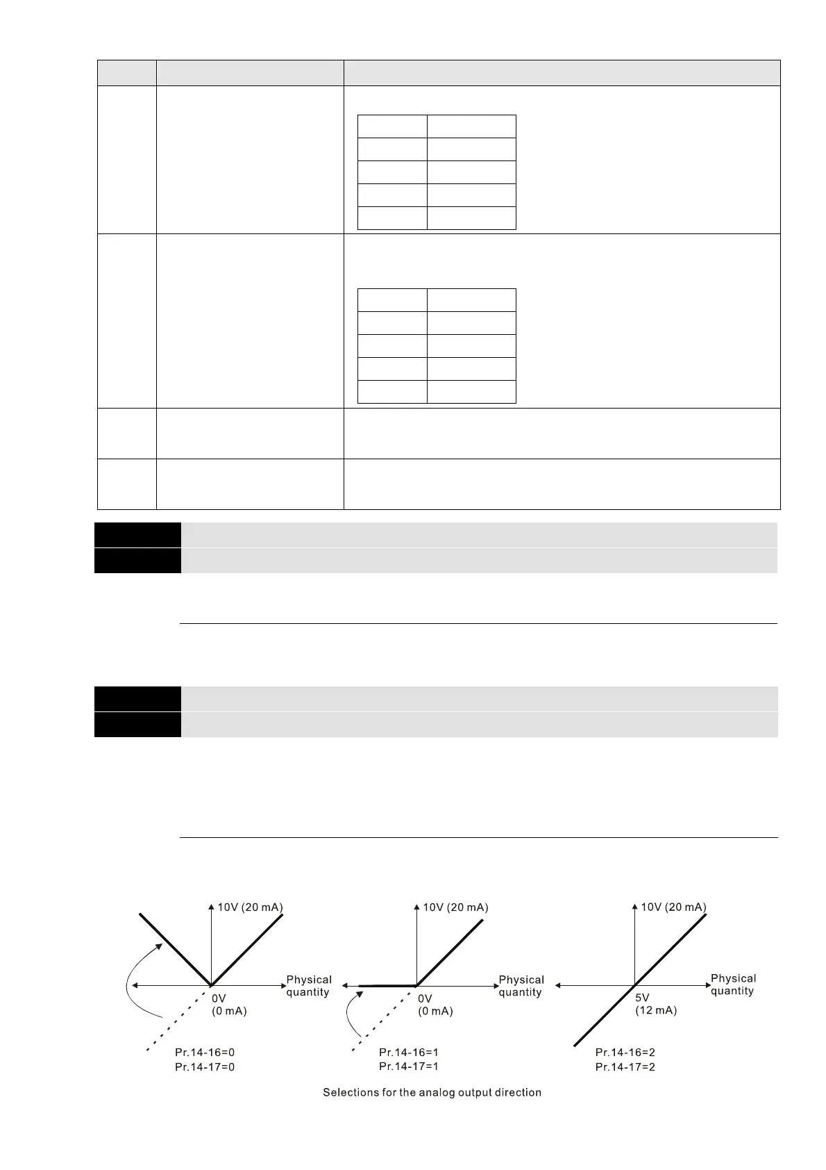
14-16
Analog Output 1 in REV Direction (AO10)
14-17
Analog Output 1 in REV Direction (AO11)
Default: 0
Settings 0: Absolute value in output voltage
1: Reverse output 0 V; forward output 0–10 V
2: Reverse output 5–0 V; forward output 5–10 V
Determine the reverse direction of output voltage when AO10 and AO11 are set as 0–10 V
(Pr.14-36 = 0, Pr.14-37 = 0).
 Loading...