CANopen Communication Module DVPCOPM-SL
Whe
n DVPCOPM-SL serves as the slave of CANopen network, the input and output mapping areas in the different
positions of the left side of PLC are shown in below table.
Of the left side of PLC (except DVP10MC11T), the position where the first DVPCOPM-SL is equipped is 1; the position
where the second one is equipped is 2; and so on. Of the left side of DVP10MC11T, the position where the first
DVPCOPM-SL is equipped is 2; the position where the second one is equipped is 3; and so on.
Mapping area
Position
Output Mapping Area Input Mapping Area
1 D6282~D6476 D6032~D6226
2 D6782~D6976 D6532~D6726
3 D7282~D7476 D7032~D7226
4 D7782~D7976 D7532~D7726
5 D8282~D8476 D8032~D8226
6 D8782~D8976 D8532~D8726
7 D9282~D9476 D9032~D9226
8 D9782~D9976 D9532~D9726
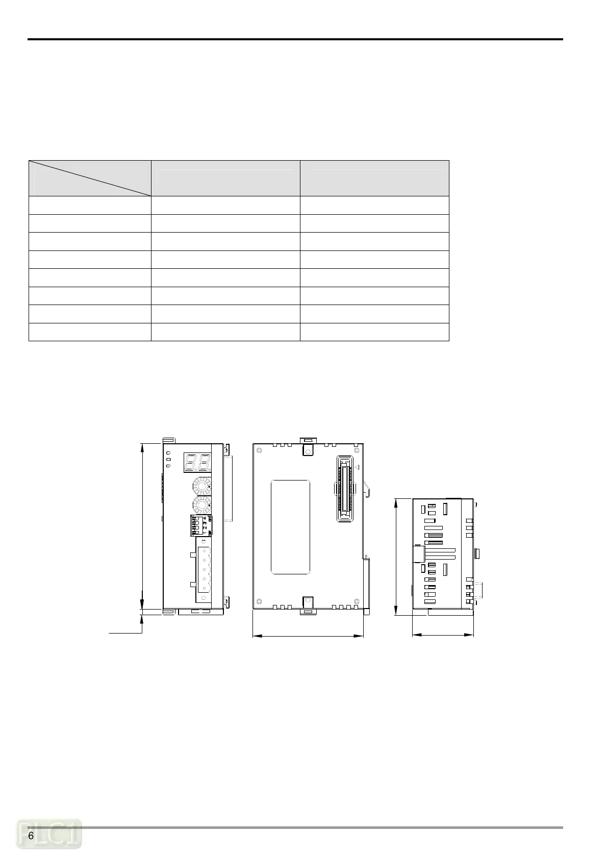
2 Product Profile & Outline
DVPCOPM-SL is composed of CANopen connection port, address switch, function switch, and digital display.
2.1 Dimension
90 [3.543]
60 [2.362]
63.4 [2.496]
33.1 [1.303]
3 [0.118]
IN 0
SHLD
GND
CAN-
DVPCOPM-SL
ERR
NODE ADDRESS
0
DR 2
DR 1
DR 0
x16
x16
1
POWER
RUN
DVP-PLC Operation Manual
6

 Loading...