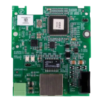
CANopen Communication Module DVPCOPM-SL
2.2 Product Profiles
3
4
7
5
8
2
9
6
6
6
1
2
IN 0
SHLD
GND
CAN-
DVPCOPM-SL
ERR
NODE ADDRESS
0
DR 2
DR 1
DR 0
x16
x16
1
POWER
RUN
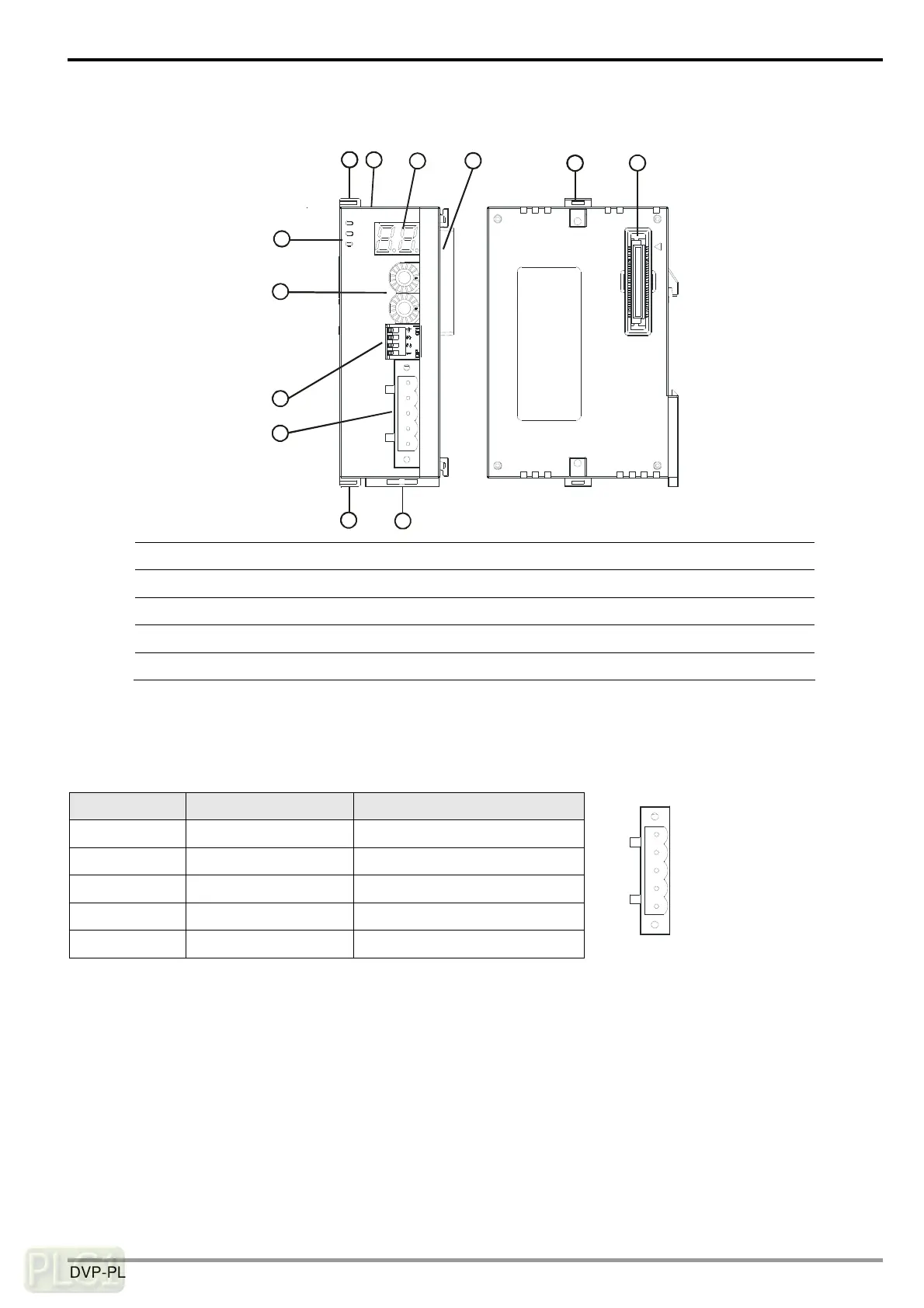
1. Model name 6. Fixing clip for I/O module
2. I/O module Interface 7. Address switch
3. POWER, RUN, ERR indicators 8. Function switch
4. DIN rail clip 9. CANopen connection port
5. Digital display
2.3 CANopen Connection Port
The connector is used on the connection to CANopen network. Wire by using the connector enclosed with
DVPCOPM-SL.
PIN Signal Content
1 GND 0 VDC
2 CAN_L Signal-
3 SHLD Shielded
4 CAN_H Signal+
5 - Reserved
4
GND
SHLD
CAN-
CAN+
5
3
2
1
DVP-PLC Operation Manual
7

 Loading...