Chapter 5 Parameters_VFD-B Series
Revision 10/2005, BE13, SW V4.08 5-57
60Hz
0Hz
0V
10V
Pr.01-00=60Hz--Max. output Freq.
Negative
bias 6.6H
1V
Bias
adjustment
AVI AUI
Pr.04-00 Pr.04-15=10.0%--Bias adjustment
Pr.04-01 Pr.04-16=1--Negative bias
Pr.04-02 Pr.04-17=111%--Input gain
Pr.04-03 Pr.04-18=0--No negative bias command
Gain:(10V/9V)*100%=111%
Bias adjustment:((6.6Hz/60Hz)/(Gain/100%))*100%=10.0%
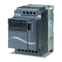
Example 7: Use of 0-10V potentiometer signal to run motor in FWD and REV direction
In this example, the input is programmed to run a motor in both forward and reverse direction. The motor will be
idle when the potentiometer position is at mid-point of its scale. Using this example will disable the external FWD
and REV controls.
Pr.01-00=60Hz--Max. output Freq.
AVI AUI
Pr.04-00 Pr.04-15=50.0%--Bias adjustment
Pr.04-01 Pr.04-16=1--Negative bias
Pr.04-02 Pr.04-17=200%--Input gain
Pr.04-03 Pr.04-18=1--Negative bias: REV motion enabled
Gain:(10V/5V)*100%=200%
Bias adjustment:((60Hz/60Hz)/(Gain/100%))*100%=200%
60Hz
30Hz
0Hz
0V
5V
10V
30Hz
60Hz
REV
FWD
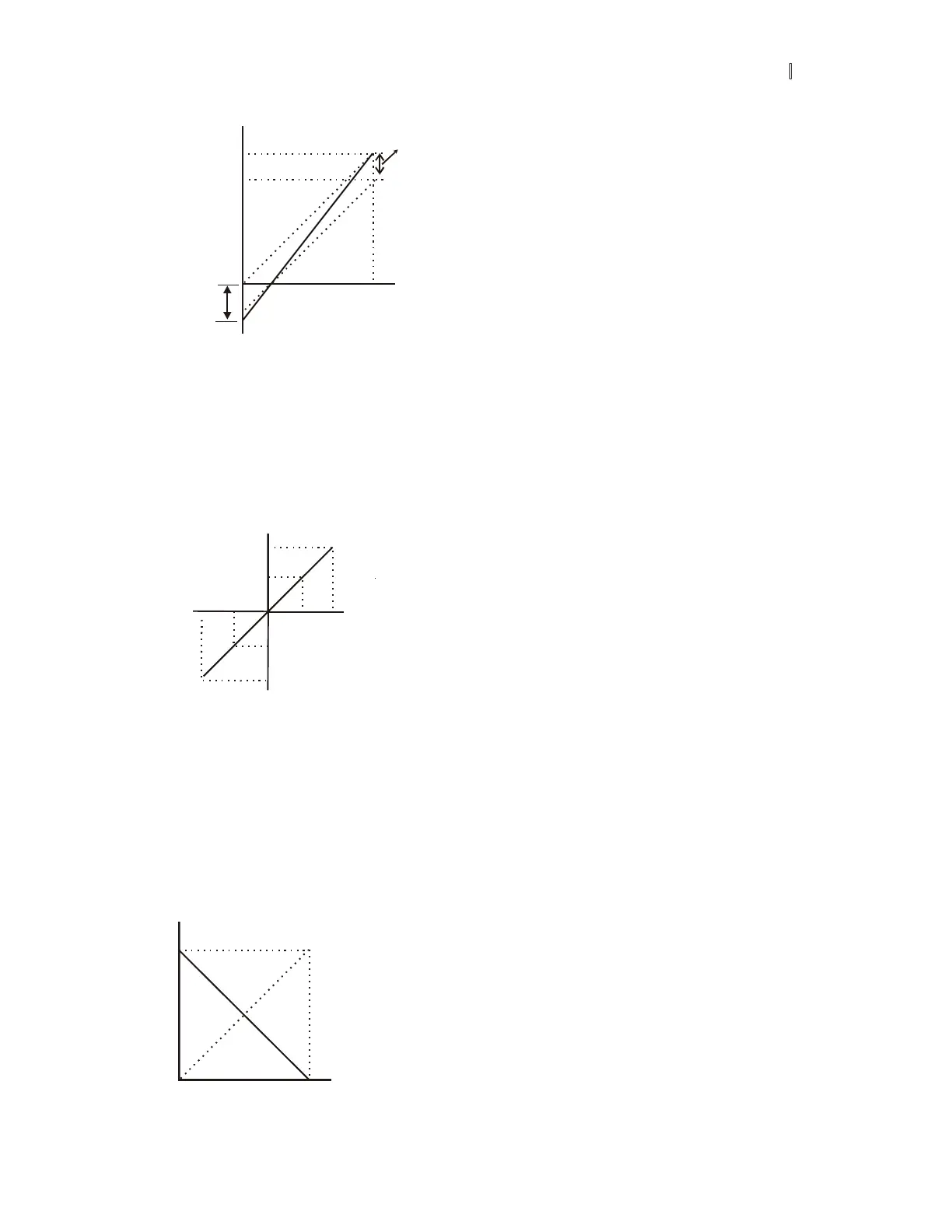
Example 8: Use negative slope
In this example, the use of negative slope is shown. Negative slopes are used in applications for control of
pressure, temperature or flow. The sensor that is connected to the input generates a large signal (10V or 20mA)
at high pressure or flow. With negative slope settings, the AC motor drive will slow stop the motor.
With these settings the AC motor drive will always run in only one direction (reverse). This can only be changed
by exchanging 2 wires to the motor.
60Hz
0Hz
0V
4m
10V
20mA
Pr.01-00=60Hz--Max. output Freq.
AVI ACI AUI
Pr.04-00 Pr.04-11 Pr.04-15=100%--Bias adjustment
Pr.04-01 Pr.04-12 Pr.04-16=0--Positive bias
Pr.04-02 Pr.04-13 Pr.04-17=100%--Input gain
Pr.04-03 Pr.04-14 Pr.04-18=1--Negative bias: REV motion enabled
Gain:(10V/10V)*100%=100%
Bias adjustment:((60Hz/60Hz)/(Gain/100%))*100%=100%
negative slope
 Loading...